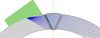
Austenitische Schweißmetalle und Nickellegierungen und andere grobkörnige anisotrope Materialien beeinträchtigen die Ultraschallausbreitung, was zu einer Schallbündelverzerrung und -streuung, Modenwandlung und deutlich erhöhten Schallschwächung und schließlich zu einem schlechten Signal-Rausch-Verhältnis führt, im Gegensatz zur Transversalwellenprüfung von niedriglegiertem Kohlenstoffstahl. Die Prüfung dieser Materialien erfordert den Einsatz von Sender/Empfänger-Phased-Array-Sensoren mit Vorlaufkeilen für gebrochene Longitudinalwellen, die die Sender- und Empfänger-Schallbündel für ein verbessertes Signal/Rausch-Verhältnis und die Unterdrückung von Vorlaufkeilechos akustisch eindämmen. Unsere Dual Linear Array (DLA) und Dual Matrix Array (DMA) Sensoren werden mit austauschbaren Vorlaufkeilen verwendet, um verschiedene Prüftechniken (wie direkte Longitudinalwellen, Oberflächenwellen, RTT (Round Trip Tandem) und andere Multi-Modus-Verfahren) für eine komplette Volumenprüfung in einem einzigen Phased-Array-S-Bild zu kombinieren. | ![]() |
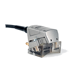
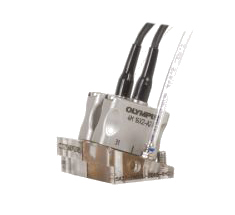
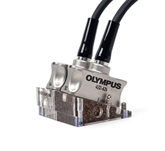
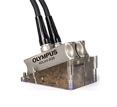
DMA-Sensoren bestehen aus zwei Phased-Array-Sensoren (PA), die mit dem gleichen Anschluss verdrahtet sind. Sie sind als Dual Matrix Array (DMA) oder Dual Linear Array (DLA) Sensoren verfügbar. Ein Sensor führt einen Sektor-Scan durch und mit dem anderen Sensor wird das vom Fehler zurückschallende Echo aufgezeichnet.
A25 | A27 | A26 | A36 | |
Frequenz | 5 MHz | 4 MHz | 2,25 MHz und 4 MHz | 2,25 MHz und 4 MHz |
---|---|---|---|---|
Konfiguration | Dual 16 (Linear) | Dual 32 (16 × 2 Matrix) | Dual 32 (Linear) | Dual 64 (Linear) |
Apertur | 12 mm × 5 mm | 16 mm × 6 mm | 32 mm × 12 mm | 64 mm × 12 mm |
Empfohlene Vorlaufkeil-Serie | SA25-DN70L-IH | SA27-DN55L-FD15-IHC | SA26-DN55L-FD40-IHC | SA36-DN55L-FD200-IHC |
Eigenschaften | Kompatibel mit dem COBRA Scanner für die Prüfung von Rohren mit kleinem Durchmesser (<10 mm Dicke) | Allgemein einsetzbar mit hervorragender Gesamtleistung und oberflächennaher Auflösung (10–40 mm Dicke) | Optimiert für sehr dicke Materialien (40–80 mm) | Optimiert für sehr dicke Materialien (>80 mm) |
Mindestanforderungen an die Geräteausstattung |
16:64PR (ein Sensor)
32:128PR (zwei Sensoren) | 32:128PR (zwei Sensoren) | 32:128PR (zwei Sensoren) | 64:128PR (ein Sensor) |
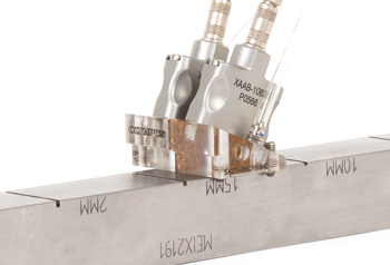
Dual UT (TRL) A27 SchallköpfeDual UT Schallköpfe für konventionellen Ultraschall können zur Prüfung mit Oberflächenwellen oder in Verbindung mit DMA-Sensoren für den kompletten Prüfbereich eingesetzt werden. Die abnehmbaren Vorlaufkeile ermöglichen eine größere Flexibilität hinsichtlich der Rohrdurchmesser und mehr Stabilität. |
Mit dem OmniScan X3 können benutzerdefinierte Dual Linear Array (DLA) oder Dual Matrix Array (DMA) Sensoren und Vorlaufkeile erstellt werden. Zusätzlich zur Erstellung von Phased-Array-Sendemodulierungen (PA) kann der Prüfplan auch zum Einstellen von Total Focusing Method (TFM)- und Phase Coherence Imaging (PCI)-Gruppen verwendet werden. Der Prüfplan unterstützt eine Vielzahl von Geometrien, einschließlich COD-Konfigurationen. |
The OmniScan flaw detector has an established track record for reliable and cost-effective phased array (PA) weld inspections as an alternative to radiography. Olympus ultrasonic weld inspection solutions provide an affordable means to inspect welds in compliance with major code and manufacturing requirements. An ideal combination of acquisition unit, scanner, encoder, and software, these solutions can be put to work virtually anywhere. Continuously improved and supported software makes the inspection of welds even easier, allowing you to complete your entire workflow more efficiently.
The Olympus weld inspection solutions applies to welds made of carbon steel or corrosion resistant alloy such as austenitic.
Phased Array Pulse-Echo Technique Phased array technique is based on the capacity to electronically modify ultrasonic beams generated by probes that contain multiple small elements. When these elements are excited using different time delays (focal laws), the beams are steered at different angles and focused at specific depths. | ![]() |
Conventional UT Pulse-Echo Technique This technique uses a single element transducer to generate an acoustic beam at a fixed angle. The echo coming back to the transducer is interpreted by the instrument to provide information on size and position. | ![]() |
Time-of-Flight Diffraction (TOFD) Technique Time-of-flight diffraction (TOFD) is an ultrasonic technique that relies on the property of defects such as cracks to diffract energy from their tips to the receiver probe when impinged by ultrasonic beams generated by the transmitter probe. TOFD technique uses a wide beam that provides good coverage and is independent of defect orientation. | ![]() |
Transmit-Receive Longitudinal Wave (TRL) This technique uses separate transmit and receive probes to generate refracted longitudinal wave. The use of separate probes minimizes vulnerability to noisy material, which is especially beneficial for inspection of coarse grain alloy, such as austenitic and nickel. | ![]() |
Surface Wave Technique The surface wave (creeping) technique is an ultrasonic test in which discontinuities are detected by the return of a creeping wave that tracks the surface of the component being tested. | ![]() |
Ultrasonic testing in lieu of radiography has proven very effective for pressure vessels, tanks, piping, and other weld configurations. Olympus ultrasonic weld inspection solutions features comply with ASME, API and other radiography replacement code requirements such as full raw data collection and the use of an encoder. Compared to conventional radiography, Olympus ultrasonic weld inspection solutions offer multiple benefits such as:
![]() |
|
ID | Type of Defect | Ultrasound (AUT) | Radiography (RT) |
1 | Toe crack |
• Position X, Y, and Z
• Length sizing • Height sizing |
• Position X and Y
• Length sizing |
2 | Centerline crack |
• Position X, Y, and Z
• Length sizing • Height sizing | • No detection |
3 | Porosity |
• Position X, Y, and Z
• Length sizing |
• Position X and Y
• Length sizing |
4 | Incomplete root penetration |
• Position X, Y, and Z
• Length sizing • Height sizing |
• Position X and Y
• Length sizing |
Olympus Ultrasonic Solutions | Radiography (RT) | |
Absence of Radiation hazard | Yes | No |
Absence of restricted area | Yes | No |
Ease of deployment on site | Yes | No |
Probability of detection (POD)
(Planar defects such as crack and lack of fusion) | Very good | Poor |
Inspection throughput | Very good | Good |
Depth sizing capability | High accuracy | Poor |
Length sizing capability | High accuracy |
Good accuracy
|
You are being redirected to our local site.