Overview
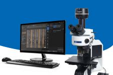
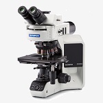
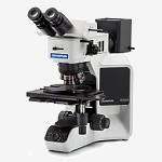
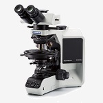
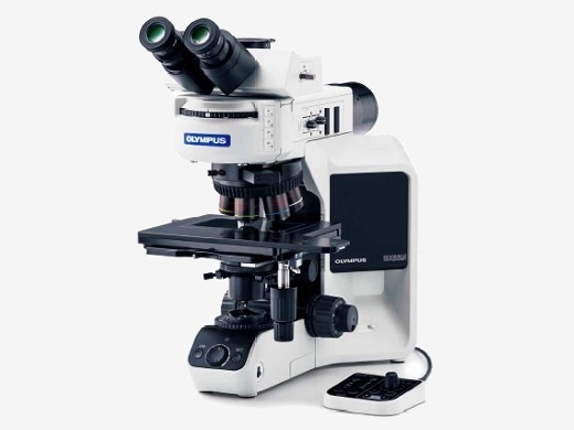
Advanced Microscopy SimplifiedDesigned with modularity in mind, the BX3M series provide versatility for a wide variety of materials science and industrial applications. With improved integration with PRECiV software, the BX53M provides a seamless workflow for standard microscopy and digital imaging users from observation to report creation. Experience BX53M | 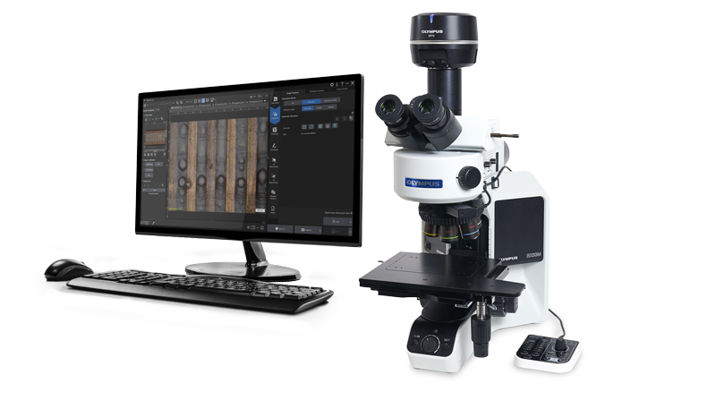 |
|---|
 | Choose the Best ModelSix BX53M suggested configuration provide you with flexibility to choose the features that you need.
See More |
|---|
Comfortable and Easy to UseThe BX53M simplifies complex microscopy tasks through its well-designed and easy-to-use controls. Users can get the most out of the microscope without the need for extensive training. The easy, comfortable operation of the BX53M also improves reproducibility by minimizing human error.
See More |
|---|
 | FunctionalThe BX53M maintains the traditional contrast methods of conventional microscopy, such as brightfield, darkfield, polarized light, and differential interference contrast. As new materials are developed, many of the difficulties associated with detecting defects using standard contrast methods can be solved using advanced microscopy techniques for more accurate and reliable inspections. New illumination techniques and options for image acquisition within PRECiV image analysis software give users more choices of how to evaluate their samples and document findings.
See More |
|---|
Leading-Edge OpticsOur history of developing high-quality optics has resulted in a record of proven optical quality and microscopes that offer excellent measurement accuracy.
See More | Wave Front Aberration Control
|
|---|
Configurations
Highly Reliable Modular SystemSix BX53M suggested configurations provide you with flexibility to choose the features that you need. |
| General Use | Dedicated Use | |||||||||
EntryEasy setup with basic features | Standard
Simple to use with
| AdvancedSupports numerous advanced features | Fluorescence
Ideally suited for
| InfraredDesigned to use infrared observation to inspect integrated circuits | PolarizationDesigned for observing birefringence characteristics | |||||
LCD color filter |
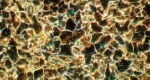
Microstructure with ferritic |
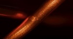
Copper wire of coil |
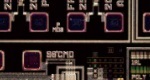
Resist on IC pattern |
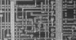
Silicon layering IC pattern |
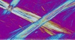
Asbestos | |||||
|
|
|
|
|
| |||||

See Specification Chart
| Entry | Standard | Advanced | Fluorescence | Infrared | Polarization | |
| Microscope frame | Reflected or Reflected/Transmitted | Reflected or Reflected/Transmitted | Reflected | Transmitted | ||
| Standard | R-BF or T-BF | R-BF or T-BF or DF | R-BF or T-BF or DF or MIX | R-BF or T-BF or DF or FL | R-BF or IR | T-BF or POL |
| Option | DIC | DIC/MIX | DIC | DIC/MIX | - | - |
| Simple illuminator | - |  | | - | - | - |
| Aperture legend | - | | | | - | |
| Coded hardware | - | | | | - | |
| Focus scale index | | | | | | |
| Light intensity manager | | | | - | - | |
| Hand switch operation |  | | | | - | - |
| MIX observation | | | | | - | - |
| Objectives | Select from 3 objectives based on your applications | Select from 3 objectives based on your applications | Objectives for IR | Objectives for POL | ||
| Stage | Select from 5 stages based on the size of your samples | Select from 5 stages based on the size of your samples | Stage for POL | |||
OBSERVATION METHOD
R-BF: Brightfield (Reflected)
*T-BF can be used when selecting Reflected/Transmitted microscope frame.
|
Example Configurations for Materials Science
Modular design enables various configurations to meet users’ requirements.
|
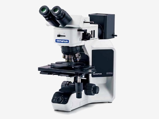
BX53M Reflected and Reflected/Transmitted Light CombinationThere are two types of microscope frames in the BX3M series, one for reflected light only and one for both reflected and transmitted light. Both frames can be configured with manual, coded, or motorized components. The frames are outfitted with ESD capability to protect electronic samples. |
BX53MRF-S example configuration |
BX53MTRF-S example configuration |
|---|
 | BX53M IR CombinationIR objectives can be used for semiconductor inspection, measurement, and processing applications where imaging through silicon is required to see the pattern. 5X to 100X infrared (IR) objectives are available with chromatic aberration correction from visible light wavelengths through the near infrared. For high magnification work, rotating the correction collar of the LCPLNIR series of lenses corrects for aberrations caused by sample thickness. A clear image is obtained with a single objective. Click here for details about IR objective lenses |
|---|
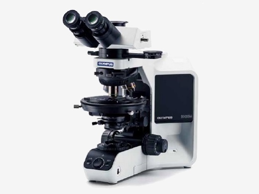
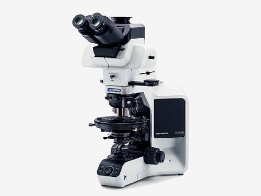
BX53M Polarized Light CombinationThe optics of the BX53M polarized light provide geologists with the right tools for high-contrast polarized light imaging. Applications such as mineral identification, investigating the optical characteristics of crystals, and observing solid rock sections benefit from system stability and precise optical alignment. |
BX53-P orthoscopic configuration |
BX53-P conoscopic/orthoscopic configuration |
|---|
Bertrand Lens for Conoscopic and Orthoscopic ObservationsWith a U-CPA conoscopic observation attachment, switching between orthoscopic and conoscopic observation is simple and fast. It is focusable for clear back focal plane interference patterns. The Bertrand field stop makes it possible to obtain consistently sharp and clear conoscopic images. | 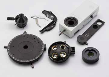 |
|---|
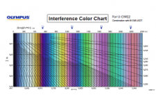
 | An Extensive Range of Compensator and Wave PlatesFive different compensators are available for measurements of birefringence in rock and mineral thin sections. Measurement retardation level ranges from 0 to 20λ. For easier measurement and high image contrast, the Berek and Senarmont compensators can be used, which change the retardation level in the entire field of view. |
|---|
Measuring Range of Compensators
|
*R = retardation level |
Strain Free OpticsThanks to our sophisticated design and manufacturing technology, the UPLFLN-P strainfree objectives reduce internal strain to the minimum. This means a higher EF value, resulting in excellent image contrast. | Click here for details about UPLFLN-P objective lensesClick here for details about PLN-P / ACHN-P objective lenses |
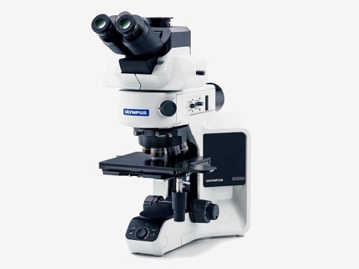
 | BXFM SystemThe BXFM can be adapted to special applications or integrated into other instruments. The modular construction provides for straightforward adaptation to unique environments and configurations with a variety of special small illuminators and fixturing mounts. |
|---|
Modular Design, Build Your System Your Way |
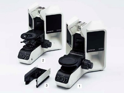
Microscope FramesThere are two microscope frames for reflected light, one also has transmitted Light; capability. An adapter is available to raise the illuminator to accommodate taller samples.
Convenient Accessories for Microscopy use
|
|
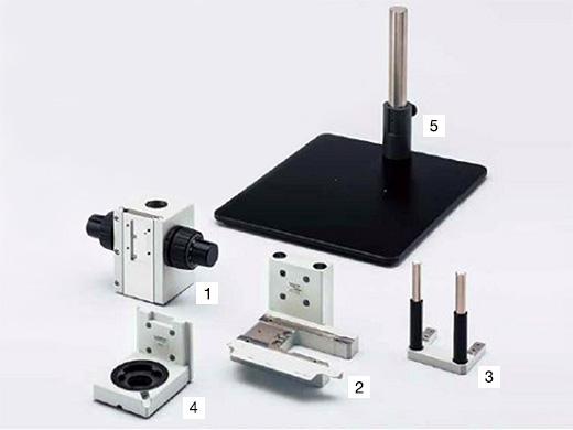
StandsFor microscopy applications where the sample will not fit on a stage, the illuminator and optics can be mounted to a larger stand or to another piece of equipment. BXFM + BX53M Illuminator Configuration
BXFM + U-KMAS Illuminator Configuration
|
|
TubesFor microscope imaging with eyepieces or for camera observation, select tubes by imaging type and operator’s posture during observation.
| 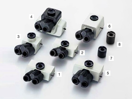 |
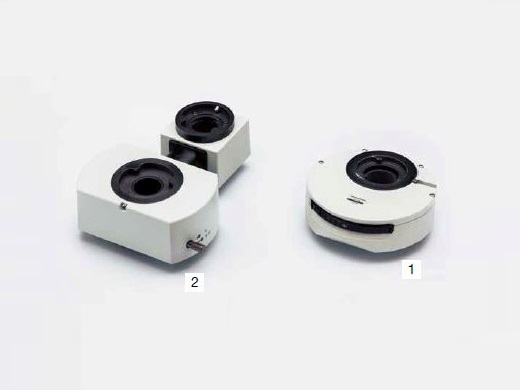
IlluminatorsThe illuminator projects light onto the sample based on the observation method selected. Software interfaces with coded illuminators to read the cube position and automatically recognize the observation method. | 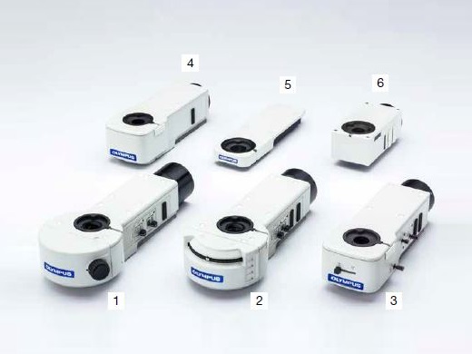 |
| Coded function | Light source | BF | DF | DIC | POL | IR | FL | MIX | AS/FS | ||
| 1 | BX3M-RLAS-S | Fixed 3 cube position | LED - Built in | ■ | ■ | ■ | ■ | - | - | ■ | ■ |
| 2 | BX3M-URAS-S | Attachable 4 cube position | LED | ■ | ■ | ■ | ■ | - | - | ■ | ■ |
| Halogen | ■ | ■ | ■ | ■ | ■ | - | ■ | ■ | |||
| Mercury/Light guide | ■ | ■ | ■ | ■ | - | ■ | ■ | ■ | |||
| 3 | BX3M-RLA-S | LED | ■ | ■ | ■ | ■ | - | - | ■ | ■ | |
| Halogen | ■ | ■ | ■ | ■ | ■ | - | ■ | ■ | |||
| 4 | BX3M-KMA-S | LED - Built in | ■ | - | ■ | ■ | - | - | ■ | - | |
| 5 | BX3-ARM | Mechanical arm for transmitted light | |||||||||
| 6 | U-KMAS | LED | ■ | - | ■ | ■ | - | - | ■ | - | |
| Halogen | ■ | - | ■ | ■ | ■ | - | ■ | - | |||
Light SourcesLight sources and power supplies for sample illumination, choose the appropriate light source for the observation method. | 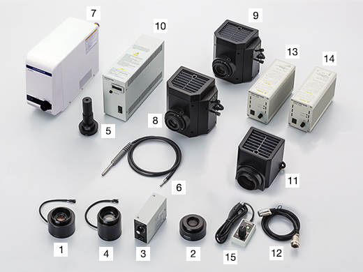 |
Standard LED Light Resource Configuration
Fluorescence Light Resource Configuration
| Halogen and Halogen IR Light Resource Configuration
|
NosepiecesAttachment for objectives and sliders. Select by the number of objectives needed and types; also with/without slider attachment. | 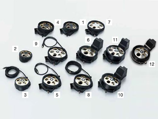 |
| Type | Holes | BF | DF | DIC | MIX | ESD |
Number of
centering holes | ||
| 1 | U-P4RE | Manual | 4 | ■ | ■ | 4 | |||
| 2 | U-5RE-2 | Manual | 5 | ■ | |||||
| 3 | U-5RES-ESD | Coded | 5 | ■ | ■ | ||||
| 4 | U-D6RE | Manual | 6 | ■ | ■ | ||||
| 5 | U-D6RES | Coded | 6 | ■ | ■ | ||||
| 6 | U-D5BDREMC | Motorized | 5 | ■ | ■ | ■ | ■ | ||
| 7 | U-D6BDRE | Manual | 6 | ■ | ■ | ■ | ■ | ||
| 8 | U-D5BDRES-ESD | Coded | 5 | ■ | ■ | ■ | ■ | ■ | |
| 9 | U-D6BDRES-S | Coded | 6 | ■ | ■ | ■ | ■ | ■ | |
| 10 | U-D6REMC | Motorized | 6 | ■ | ■ | ||||
| 11 | U-D6BDREMC | Motorized | 6 | ■ | ■ | ■ | ■ | ■ | |
| 12 | U-D5BDREMC-VA | Motorized | 5 | ■ | ■ |
SlidersSelect the slider to compliment traditional brighfield observation. The DIC slider provides topographic information about the sample with options to maximize contrast or resolution. The MIX slider provides illumination flexibility with a segmented LED source in the darkfield path. |  |
DIC Slider
*1 1.25X and 2.5X do not support DIC observation.
MIX Slider
| Cable
*MIXR only |
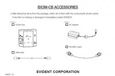
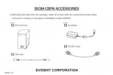
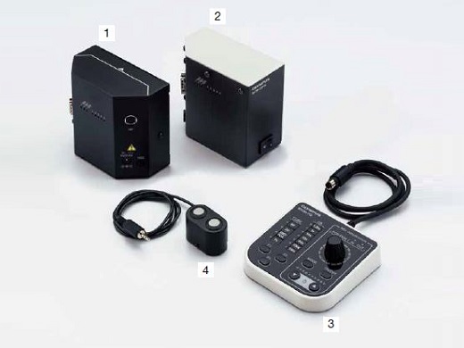
Controls Box and Hand SwitchesControl boxes for interfacing microscope hardware with a PC and hand switches for hardware display and control. BX3M-CB (CBFM) Configuration
Cable
|
|
StagesStages and stage plates for sample placement. Select based on sample shape and size. | 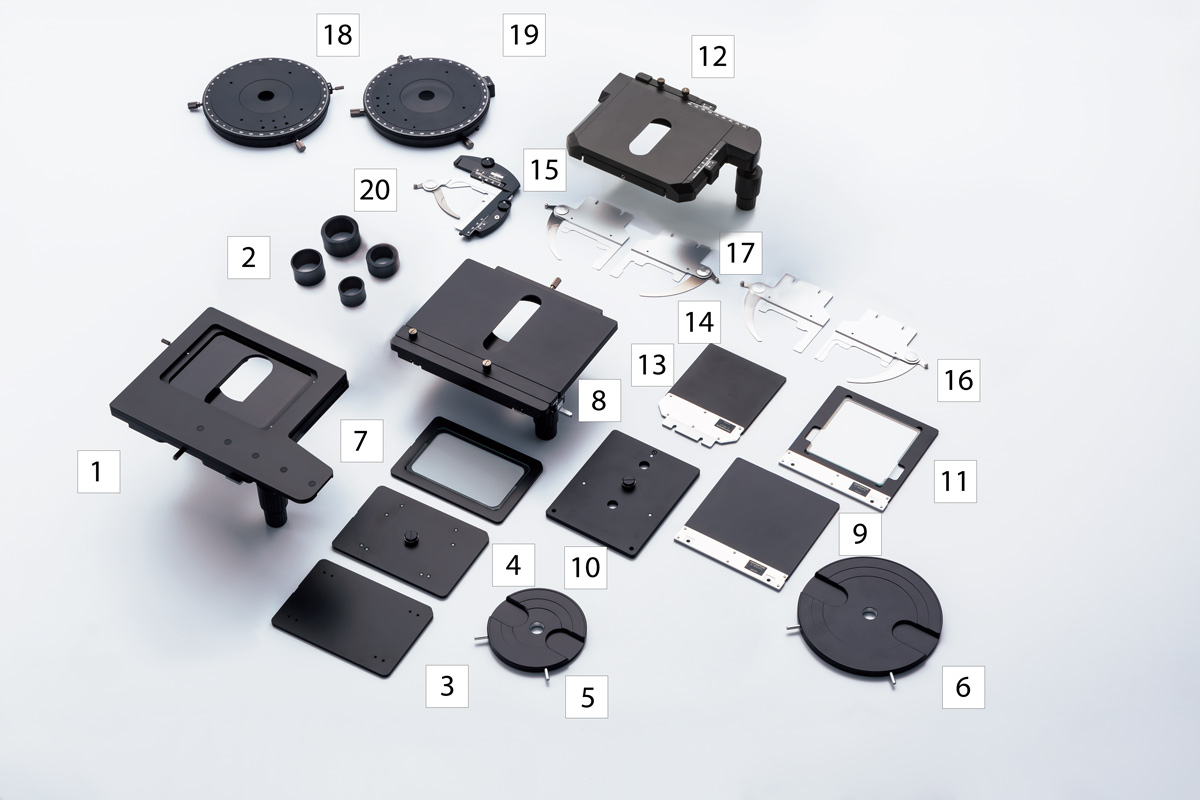 |
150 mm × 100 mm Stage Configuration
76 mm × 52 mm Stage Configuration
| 100 mm × 100 mm Stage Configuration
Others
|
Camera AdaptersAdapter for camera observation. Selectable from required field of view and magnification. Actual observation range can be calculated using this formula: actual field of view (diagonal mm) = viewing field (viewing number) ÷ objective magnification. | 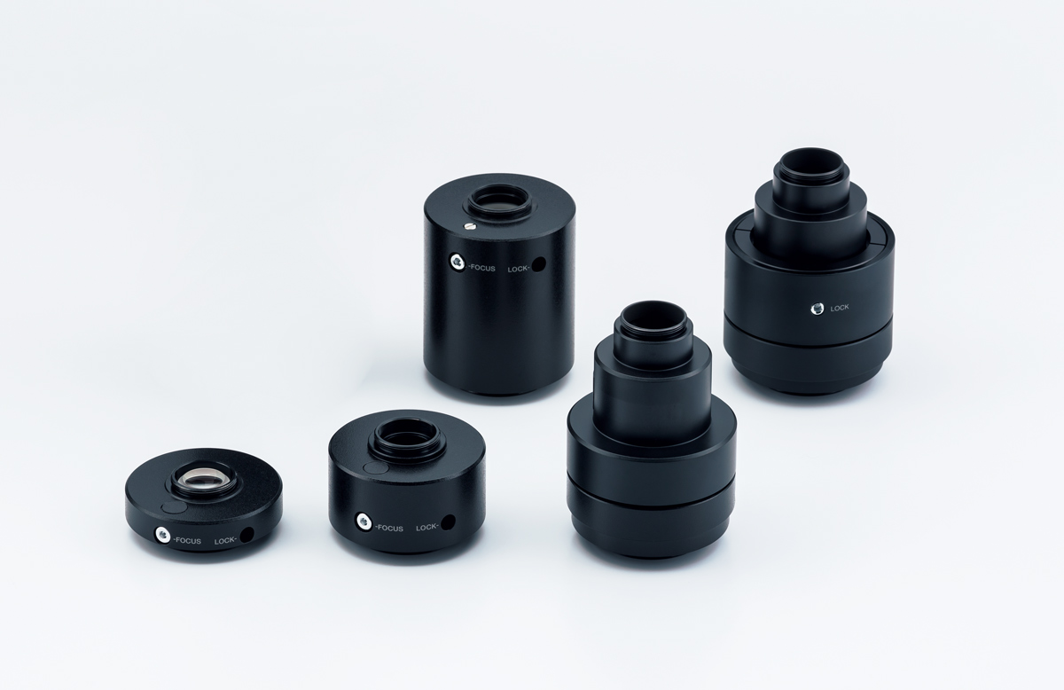 |
| Magnification | Centering adjustment | CCD image area (field number) mm | ||||
| 2/3 inch | 1/1.8 inch | 1/2 inch | ||||
| 1 | U-TV1x-2 with U-CMAD3 | 1 | - | 10.7 | 8.8 | 8 |
| 2 | U-TV1xC | 1 | ø2 mm | 10.7 | 8.8 | 8 |
| 3 | U-TV0.63xC | 0.63 | - | 17 | 14 | 12.7 |
| 4 | U-TV0.5xC-3 | 0.5 | - | 21.4 | 17.6 | 16 |
| 5 | U-TV0.35xC-2 | 0.35 | - | - | - | 22 |
EyepiecesEyepiece for viewing directly into the microscope. Select based on desired field of view.
| 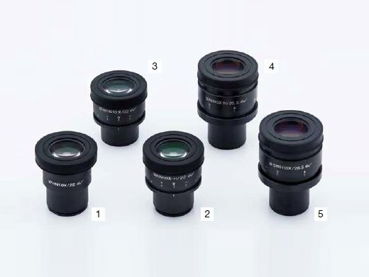 |
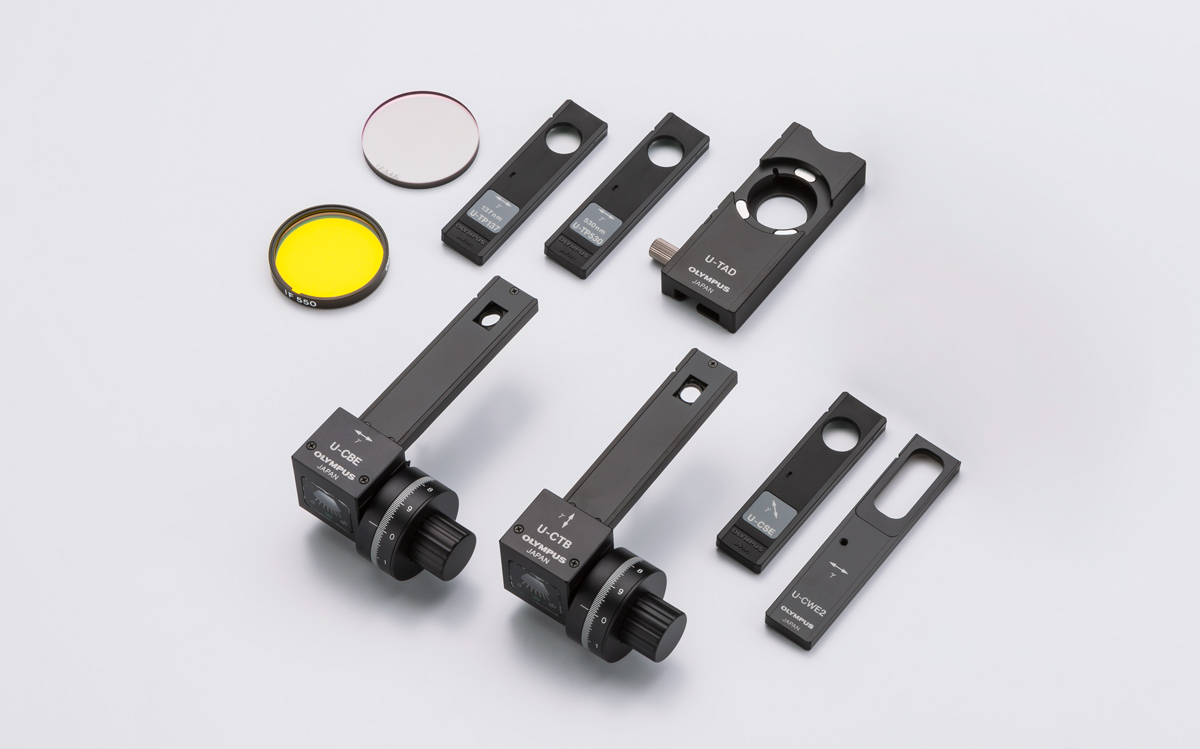
Optical FiltersOptics filters convert sample exposure light to various types of illumination. Select the appropriate filter for observation requirements. | |
BF, DF, FL
POL, DIC
| IR
Transmitted Light
Others
*AN and PO are not necessary when using BX3M-RLAS-S and U-FDICR |
CondensersCondensers collect and focus transmitted light. Use for transmitted light observation.
| 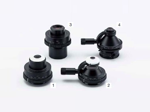 |
Mirror UnitsMirror unit for BX3M-URAS-S. Select the unit for required observation.
*For coaxial episcopic illumination only | 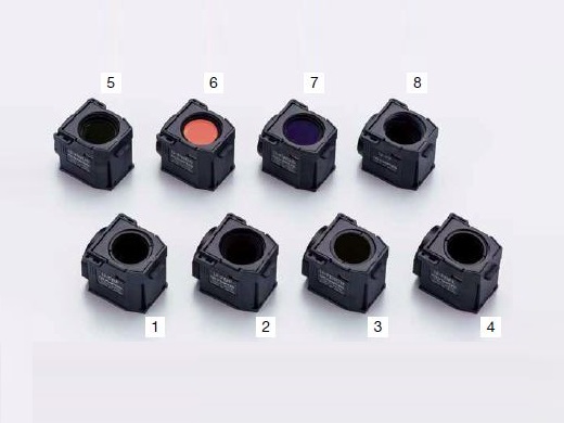 |
Intermediate TubesVarious types of accessories for multiple purposes. For use between tube and illuminator.
|  |
UIS2 ObjectivesObjectives magnify the sample. Select the objective that matches the working distance, resolving power and observation method for the application. |
Ease of Use
Traditional Techniques Made Easy:
|
|---|
 |
Intuitive Microscope Controls:
|
|---|
Find the Focus QuicklyThe focus scale index on the frame supports quick access to the focal point. Operators can roughly adjust the focal point without viewing the sample through an eyepiece, saving time when inspecting samples that are different heights. | 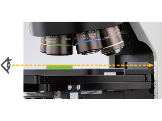 |
|---|
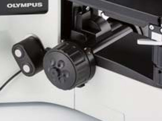 | 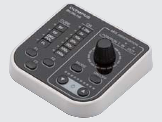 | Easy and Comfortable OperationA system design affects users' work efficiency. Both standalone microscope users and those integrating with PRECiV image analysis software benefit from convenient handset controls that clearly display the hardware position. The simple handsets enable the user to focus on their sample and the inspection they need to perform. |
|---|
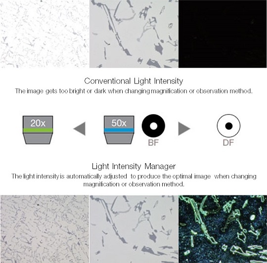
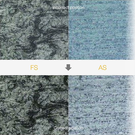
For Consistent Illumination:
|  |
|---|
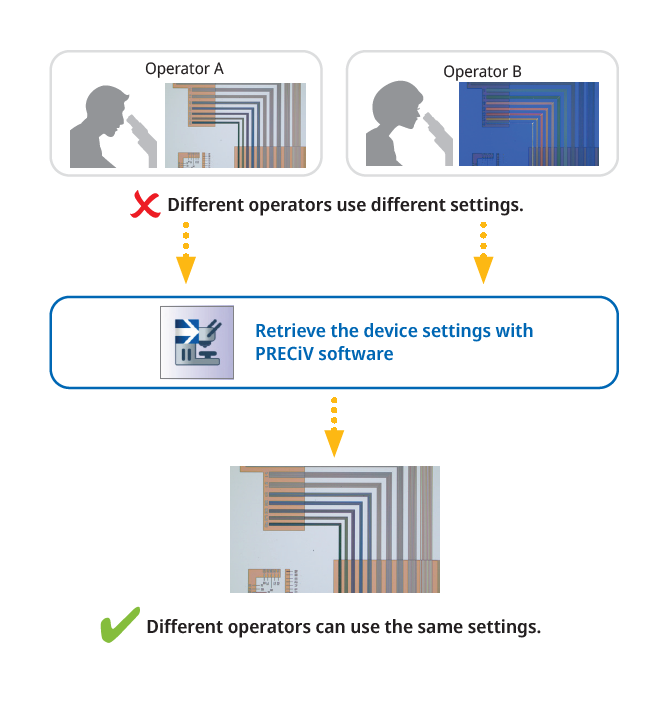 |
For Restoring Microscope Settings:
|
|---|
Functionality
The Invisible Becomes Visible:
|  |
|---|
 | Create All-in-focus Images: EFIThe Extended Focus Imaging (EFI) function within PRECiV software captures images of samples whose height extends beyond the depth of focus of the objective and stacks them together to create one image that is all in focus. EFI can be executed with either a manual or motorized Z-axis and creates a height map for easy structure visualization. It is also possible to construct an EFI image while offline within PRECiV Desktop. |
|---|
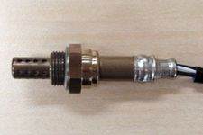
Capture Both Bright and Dark Areas: HDRUsing advanced image processing, high dynamic range (HDR) adjusts for differences in brightness within an image to reduce glare. HDR improves the visual quality of digital images thereby helping to generate professional-looking reports. | 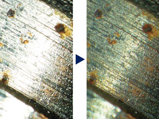 Clearly exposed for both of dark and bright parts by HDR (Sample: fuel injector bulb) | 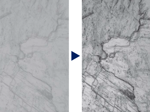 Contrast enhancement by HDR |
|---|
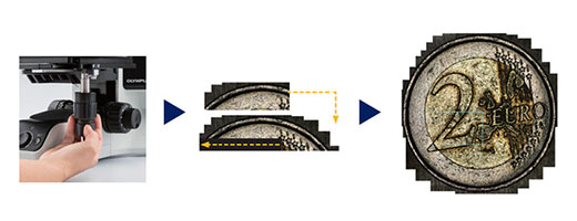 Instant MIA image of a coin | Easily Move the Stage for Panorama: Instant MIAYou can now stitch images easily and quickly just by moving the XY knobs on the manual stage; no motorized stage is necessary. PRECiV software uses pattern recognition to generate a panoramic image giving users a wider field of view than a single frame. |
|---|
Versatile Measurement Capability |
Routine or Basic Measurement FunctionsVarious measurement functions are available through PRECiV so that the user can easily obtain useful data from the images. For quality control and inspection, measuring features on images are often required. All levels of PRECiV licenses include interactive measurement functions such as distances, angles, rectangles, circles, ellipses, and polygons. All measured results are saved with the image files for further documentation. | 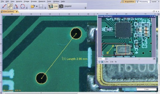 |
|---|
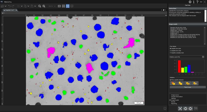 | Count and MeasureObject detection and size distribution measurement are among the most important applications in digital imaging. PRECiV incorporates a detection engine that utilizes threshold methods to reliably separate objects (e.g., particles, scratches) from the background. |
|---|
Materials Science SolutionsPRECiV offers an intuitive, workflow-oriented interface for complex image analysis. At the click of a button, the most complex image analysis tasks can be executed quickly, precisely, and in compliance with most common industrial standards. With a significant reduction in processing time for repeated tasks, materials scientists can concentrate on analysis and research. Modular add-ins for inclusions and intercept charts are easily performed at any time. | 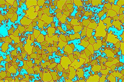 |
|---|
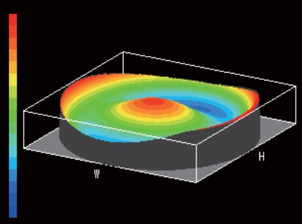
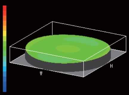
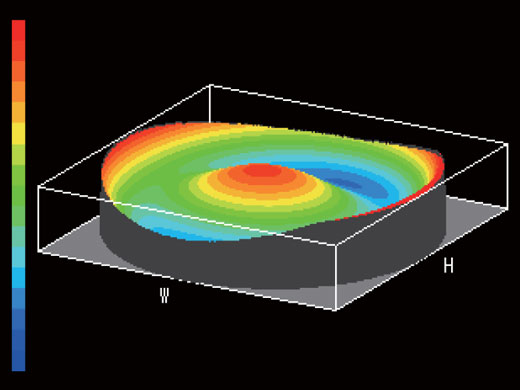
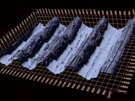 3D surface view (Roughness test sample) | 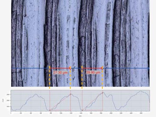 Single view and 3D profile measurement | 3D Sample MeasurementWhen using an external motorized focus drive, an EFI image can be quickly captured and displayed in 3D. The height data acquired can be used for 3D measurements on the profile or from the single view image. |
|---|
Learn More about PRECiV |
View More Sample Types and SizesThe new 150 × 100 mm stage provides a longer travel in the X direction than previous models. This, together with the flat-top design, enables large samples or multiple samples to be easily placed on the stage. The stage plate has tapped holes to attach a sample holder. The larger stage provides flexibility to users by enabling them to inspect more samples on one microscope, saving valuable lab space. The stage’s adjustable torque facilitates fine positioning under high magnification with a narrow field of view. |
Flexibility for Sample Height and WeightSamples up to 105 mm can be mounted on the stage with the optional modular unit. Due to the improved focusing mechanism, the microscope can accommodate a total weight (sample + stage) of up to 6 kg. This means that larger and heavier samples can be inspected on the BX53M, so fewer microscopes are required in the lab. By strategically positioning a rotatable holder for 6-inch wafers off-center, users can observe the whole wafer surface by just rotating the holder when moving through the 100 mm travel range. The stage's torque adjustment is optimized for ease of use and the comfortable handle grip makes it easy to find the region of interest of the sample. | 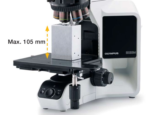 BX53MRF-S |
|---|
 BXFM | Flexibility for Sample SizeWhen samples are two large to place on a traditional microscope stage, the core optical components for reflected light microscopy can be configured in a modular configuration. This modular system, the BXFM, can be mounted to a larger stand via a pole or mounted to another instrument of choice using a mounting bracket. This enables users to take advantage of our renowned optics even when their samples are unique in size or shape. |
|---|
Protect Electronic Devices from Electrostatic Discharge: ESD CompatibleThe BX53M has an ESD dissipation capability that protects electronic devices from static electricity caused by human or environmental factors. |
Image Quality
A History of Leading-Edge Optics |
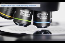
Combined high numerical aperture and long working distance
Objective lenses are crucial to a microscope’s performance.
|
|
|
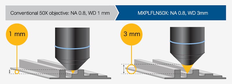
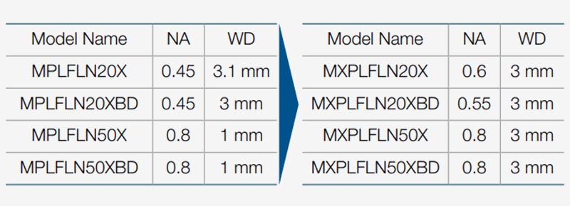
Learn More about MXPLFLN Objectives |
Superior Optical Performance:
|  Bad wavefront | 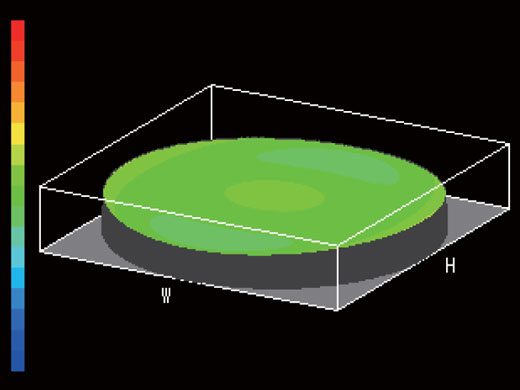 Good wavefront (UIS2 objective) |
|---|
 Halogen lamp: Color varies with light intensity. |  LED: Color is consistent with light intensity and clearer than halogen lamp. |
Consistent Color Temperature:
|
|---|
Superior Quality for Advanced Performance |
Support Precise Measurement:
|  |
|---|
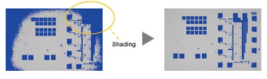 Semiconductor wafer (Binarized image): |
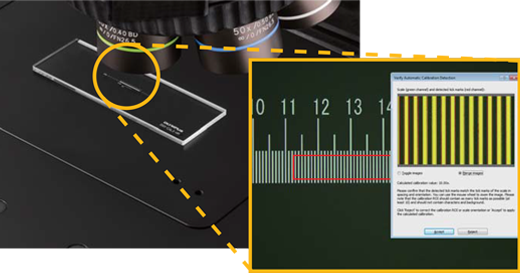
Seamless Stitching:
|
|---|
Learn More about PRECiV |
Applications
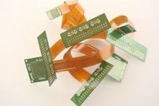
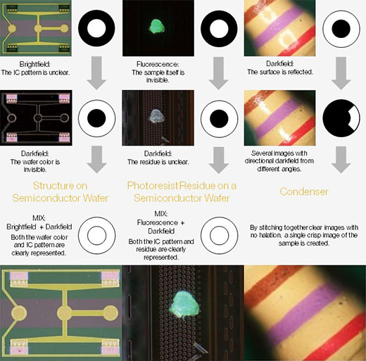
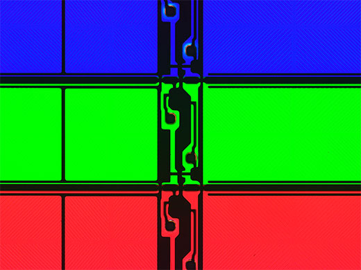
IC Pattern on a Semiconductor WaferDarkfield is used for detecting minute scratches or flaws on a sample or inspecting samples with mirrored surfaces, such as wafers. MIX illumination enables users to view both patterns and colors. |
MIX (Brightfield + Darkfield) |
Darkfield |
|---|
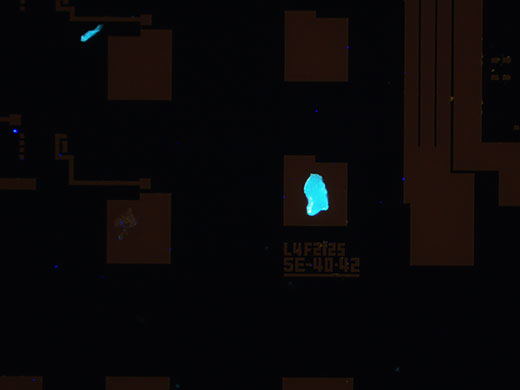
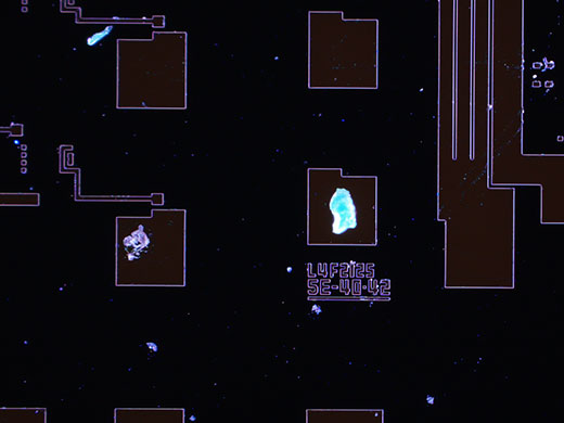
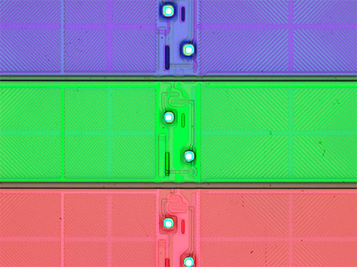
Fluorescence |
MIX (Fluorescence + Darkfield) | Photoresist Residue on a Semiconductor WaferFluorescence is used for samples that emit light when illuminated with a specially designed filter cube. This is used to detect contamination and photoresist residue. MIX illumination enables the observation of both the photoresist residue and IC pattern. |
|---|
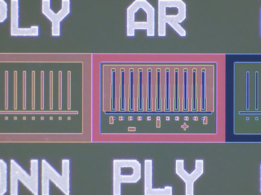
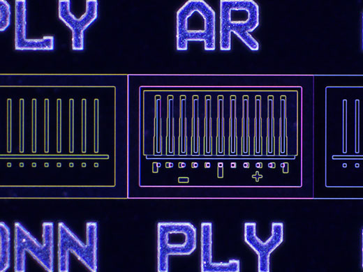
LCD Color FilterThis observation technique is suitable for transparent samples such as LCDs, plastics, and glass materials. MIX illumination enables the observation of both the filter color and circuit pattern. |
Transmitted Light |
MIX (Transmitted Light + Brightfield) |
|---|
Brightfield |
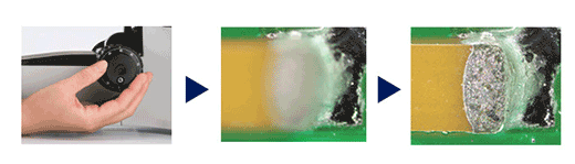
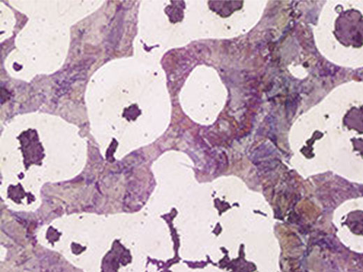
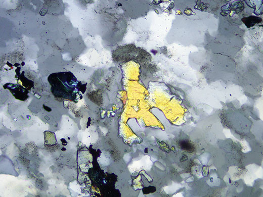
Differential Interference Contrast (DIC) | Spheroidal Graphite Cast IronDIC is an observation technique where the height of a sample is visible as a relief, similar to a 3D image with improved contrast; it is ideal for inspections of samples that have very minute height differences, including metallurgical structures and minerals. |
|---|
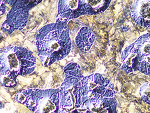
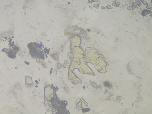
SericiteDifferential interference contrast (DIC) is an observation technique where the height of a sample, normally not detectable in brightfield, is visible as a relief, similar to a 3D image with improved contrast. It is ideal for inspections of samples that have very minute height differences, including metallurgical structures and minerals. |
Brightfield |
Polarized Light |
|---|
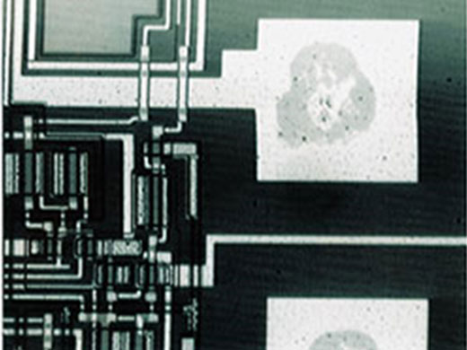
Infrared (IR) | Bonding Pads on a IC PatternIR is used to look for defects inside IC chips and other devices made with silicon on glass. |
|---|
Specifications
SPECIFICATIONS OF BX53M SUGGESTED CONFIGURATION FOR GENERAL USE |
| Entry | Standard | Advanced | |||||||
| Optical system | UIS2 optical system (infinity-corrected) | ||||||||
| Main unit | Microscope frame | BX53MRF-S (Reflected) | BX53MTRF-S (Reflected/Transmitted) | BX53MRF-S (Reflected) | BX53MTRF-S (Reflected/Transmitted) | BX53MRF-S (Reflected) | BX53MTRF-S (Reflected/Transmitted) | ||
| Focus |
Stroke: 25 mm
Fine stroke per rotation: 100 μm Minimum graduation: 1 μm With upper limit stopper, torque adjustment for coarse handle | ||||||||
| Max. specimen height |
Reflected: 65 mm (w/o spacer), 105 mm (with BX3M-ARMAD)
Reflected/Transmitted: 35 mm (w/o spacer), 75 mm (with BX3M-ARMAD) | ||||||||
| Observation tube | Wide field (F.N.22) | U-TR30-2-2 Inverted: trinocular | |||||||
| Illumination |
Reflected light
Transmitted light | BX3M-KMA-S White LED, BF/DIC/POL/MIX FS, AS (with centering mechanism), BF/DF interlocking | BX3M-RLAS-S Coded, White LED, BF/DF/DIC/POL/MIX FS, AS (with centering mechanism), BF/DF interlocking | ||||||
| - | BX3M-LEDT White LED Abbe/long working distance condensers | - | BX3M-LEDT White LED Abbe/long working distance condensers | - | BX3M-LEDT White LED Abbe/long working distance condensers | ||||
| Revolving nosepiece | U-5RE-2 For BF: Quintuple | U-D6BDRE For BF/DF: Sextuple | U-D6BDRES-S For BF/DF : Sextuple, Coded | ||||||
| Eyepiece(F.N.22) | WHN10
WHN10X-H | ||||||||
| MIX observation | - | BX3M-CB Control box BX3M-HS Hand switch U-MIXR-2 MIX slider for reflected light observation U-MIXRCBL Cable for MIXR | |||||||
| Condenser (Long working distance) | - | U-LWCD | - | U-LWCD | - | U-LWCD | |||
| Power cable | UYCP (x1) | UYCP (x2) | |||||||
| Weight |
Reflected: approx.15.8 kg (microscope frame 7.4 kg)
Reflected/transmitted: approx. 18.3 kg (microscope frame 7.6 kg) | ||||||||
| Objectives | MPLFLN set | MPLFLN5X, 10X, 20X, 50X, 100X BF/POL/FL observation | - | ||||||
| MPLFLN BD set | - | MPLFLN5XBD, 10XBD, 20XBD, 50XBD, 100XBD BF/DF/DIC/POL/FL observation | |||||||
| MPLFLN-BD, LMPLFLN-BD set | - | MPLFLN5XBD, 10XBD, LMPLFLN20XBD, 50XBD, 100XBD BF/DF/DIC/POL/FL observation | |||||||
| MPLFLN-BD, MXPLFLN-BD, LMPLFLN-BD set | - | MPLFLN5XBD, 10XBD, MXPLFLN20XBD, 50XBD, LMPLFLN20XBD, 50XBD, 100XBD BF/DF/DIC/POL/FL observation | |||||||
| Stage (X x Y) | 76 mm x 52 mm set | U-SVRM, U-MSSP Coaxial right handle stage / 76 (X) × 52 (Y) mm, with torque adjustment | |||||||
| 100 mm x 10 0mm set | U-SIC4R2, U-MSSP4 Large-size coaxial right handle stage / 100 (X) x 100 (Y) mm, with lock mechanism in Y axis | ||||||||
| 100 mm x 100 (G) mm set | U-SIC4R2, U-MSSPG Large-size coaxial right handle stage / 100 (X) x 100 (Y) mm, with lock mechanism in Y axis (Glass plate) | ||||||||
| 150 mm x 100 mm set | U-SIC64, U-SHG, U-SP64 Large-size coaxial right handle stage / 150 (X) x 100 (Y) mm, with torque adjustment, with lock mechanism in Y axis | ||||||||
| 150 mm x 100 (G) mm set | U-SIC64, U-SHG, U-SPG64 Large-size coaxial right handle stage / 150 (X) x 100 (Y) mm, with torque adjustment, with lock mechanism in Y axis (Glass plate) | ||||||||
| Option | MIX observation set* | BX3M-CB, BX3M-HS, U-MIXR-2, U-MIXRCBL | - | ||||||
| DIC* | U-DICR | ||||||||
| Intermediate Tubes | U-CA, U-EPA2, U-TRU | ||||||||
| Filters | U-25ND6, U-25ND25, U-25LBD, U-25LBA, U-25Y48, U-AN360-3, U-AN360P, U-PO3, U-25IF550, U-25L42, U-25, U-25FR | ||||||||
| Filter for condenser | 43IF550-W45, U-POT | ||||||||
| Stage plate | U-WHP64, BH2-WHR43, BH2-WHR65, U-WHP2 | ||||||||
| Specimen holder | U-HRD-4, U-HLD-4, U-HRDT-4, U-HLDT-4 | ||||||||
| Handle rubber | U-SHG, U-SHGT | ||||||||
*Cannot be used with U-5RE-2.
BX53M / BXFM ESD UNITS
| Items | Microscope frame | BX53MRF-S, BX53MTRF-S |
| Illuminator | BX3M-KMA-S, BX3M-RLA-S, BX3M-URAS-S, BX3M-RLAS-S | |
| Nosepiece | U-D6BDREMC, U-D6BDRES-S, U-D5BDREMC-ESD, U-5RES-ESD | |
| Stage | U-SIC4R2, U-MSSP4 |
SPECIFICATIONS OF BX53M SUGGESTED CONFIGURATION FOR DEDICATED USE |
| Fluorescence | Infrared | Polarized | |||||
| Optical system | UIS2 optical system (infinity-corrected) | ||||||
| Main unit | Microscope frame | BX53MRF-S (Reflected) | BX53MTRF-S (Reflected/ Transmitted) | BX53MRF-S (Reflected) | BX53MTRF-S (Reflected/Transmitted) | ||
| Focus |
Stroke: 25 mm
Fine stroke per rotation: 100 μm Minimum graduation: 1 μm With upper limit stopper, torque adjustment for coarse handle | ||||||
| Max. specimen height |
Reflected: 65 mm (w/o spacer), 105 mm (with BX3M-ARMAD)
Reflected/Transmitted: 35 mm (w/o spacer), 75 mm (with BX3M-ARMAD) | ||||||
| Observation tube | Wide field (F.N.22) | U-TR30-2 Inverted: trinocular | U-TR30IR Inverted: trinocular for IR | U-TR30-2 Inverted: trinocular | |||
| Polarized Light Intermediate Attachment (U-CPA) | Bertrand Lens | - | - | Focusable | |||
| Bertrand Field Stop | - | - | ø3.4 mm diameter (fixed) | ||||
| Engage or disengage Bertrand lens changeover between orthoscopic and conoscopic observation | - | - |
Position of slider ● in
Position of slider ○ out | ||||
| Analyzer Slot | - | - | Rotatable Analyzer with Slot (U-AN360P-2) | ||||
| Illumination | Reflected light | FL observation | BX3M-URAS-S Coded universal reflected light, 4 position mirror unit turret, (standard: U-FWUS, U-FWBS, U-FWGS, U-FBF etc) With FS, AS (with centering mechanism), With shutter mechanism | - | - | ||
| IR observation | - | BX3M-RLA-S 100W halogen lamp for IR, BF/IR, AS (with centering mechanism) U-LH100IR (Including 12V 10W HAL-L) 100W Halogen light source for IR TH4-100 100W power supply TH4-HS Hand switch U-RMT Extension cord | - | ||||
| Transmitted light | POL observation | - | - | BX3M-LEDT White LED Abbe/long working distance condensers | |||
| Revolving nosepiece | U-D6BDRES-S For BF/DF : Sextuple, Coded | U-5RE-2 For BF : Quintuple | U-P4RE Quadruple, centerable attachable components 1/4 wavelength retardation plate (U-TAD), tint plate (U-TP530) and various compensators can be attached using plate adapter (U-TAD) | ||||
| Eyepiece(F.N.22) | WHN10X | ||||||
| WHN10X-H | CROSS-WHN10X | ||||||
| Mirror units | U-FDF For DF U-FBFL For BF, built-in ND filter U-FBF For BF, detachable ND filter U-FWUS For Ultra Violet-FL U-FWBS For Blue-FL U-FWGS For Green-FL | - | |||||
| Filter / Polarizer / Analyzer | U-25FR Frost filter | U-BP1100IR/U-BP1200IR Band path filters for IR | 43IF550-W45 Green filter | ||||
| U-POIR Reflected polarizer slider for IR | U-AN360IR Rotatable analyzer slider for IR | U-AN360P-2 360° Dial-rotatable Rotatable minimum angle 0.1° | |||||
| Condenser | U-LWCD Long working distance | - | U-POC-2 Achromat strain-free condenser. 360°rotatable polarizer with swing-out achromatic top-lens. Click stop at position "0°" is adjustable. NA 0.9 (top-lens in) / NA 0.18 (top-lens out) Aperture iris diaphragm: adjustable from 2 mm to 21 mm diameters | ||||
| Slider / Compensators | - | U-TAD Slider (Plate adapter) | |||||
| U-TP530 Tint plate U-TP137 1/4 wavelength retardation plate | |||||||
| Power cable | UYCP (x1) | UYCP (x2) | UYCP (x1) | ||||
| Weight | Reflected: approx.15.8 kg (microscope frame 7.4 kg) | Reflected/transmitted: approx. 18.3 kg (microscope frame 7.6 kg) | Approx.18.9 kg (microscope frame 7.4 kg) | Approx.16.2 kg (microscope frame 7.6 kg) | |||
| Reflected FL light source | Light guide | U-LGPS, U-LLGAD, U-LLG150, Light guide set | - | - | |||
| Mercury lamp | U-LH100HGAPO1-7, USH-103OL (x2), U-RFL-T, U-RCV Mercury lamp set | - | - | ||||
| Objectives | MPLFLN set | MPLFLN5X, 10X, 20X, 50X, 100X BF/DIC/POL/FL observation | - | - | |||
| MPLFLN BD set | MPLFLN5XBD, 10XBD, 20XBD, 50XBD, 100XBD BF/DF/DIC/POL/FL observation | - | - | ||||
| MPLFLN-BD, LMPLFLN-BD set | MPLFLN5XBD, 10XBD, LMPLFLN20XBD, 50XBD, 100XBD BF/DF/DIC/POL/FL observation | - | - | ||||
| MPLFLN-BD, MXPLFLN-BD, LMPLFLN-BD set | MPLFLN5XBD, 10XBD, MXPLFLN20XBD, 50XBD, LMPLFLN20XBD, 50XBD, 100XBD BF/DF/DIC/POL/FL observation | - | - | ||||
| IR set | - | LMPLN5XIR,10XIR,LCPLN20XIR,50XIR,100XIR IR observation | - | ||||
| POL set | - | - | UPLFLN4XP,10XP,20XP,40XP POL observation | ||||
| Stage (X x Y) | 76 mm x 52 mm set | U-SVRM, U-MSSP Coaxial right handle stage / 76 (X) × 52 (Y) mm, with torque adjustment | |||||
| 100 mm x 10 0mm set | U-SIC4R2, U-MSSP4 Large-size coaxial right handle stage / 100 (X) x 100 (Y) mm, with lock mechanism in Y axis | ||||||
| 100 mm x 100 (G) mm set | U-SIC4R2, U-MSSPG Large-size coaxial right handle stage / 150 (X) x 100 (Y) mm, with lock mechanism in Y axis (Glass plate) | ||||||
| 150 mm x 100 mm set | U-SIC64, U-SHG, U-SP64 Large-size coaxial right handle stage / 150 (X) x 100 (Y) mm, with torque adjustment, with lock mechanism in Y axis | ||||||
| 150 mm x 100 (G) mm set | U-SIC64, U-SHG, U-SPG64 Large-size coaxial right handle stage / 150 (X) x 100 (Y) mm, with torque adjustment, with lock mechanism in Y axis (Glass plate) | ||||||
| POL set | - | U-SRP+U-FMP Polarizing rotatable stage + Mechanical stage | |||||
| Option | MIX observation set* | BX3M-CB, BX3M-HS, U-MIXR-2, U-MIXRCBL | |||||
| DIC* | U-DICR | ||||||
| Intermediate Tubes | U-CA, U-EPA2, U-TRU | ||||||
| Filters | U-25ND6, U-25ND25, U-25LBD, U-25LBA, U-25Y48, U-AN360-3, U-AN360P, U-PO3, U-25IF550, U-25L42, U-25, U-25FR | ||||||
| Filter for condenser | 43IF550-W45, U-POT | ||||||
| Stage plate | U-WHP64, BH2-WHR43, BH2-WHR65, U-WHP2 | ||||||
| Specimen holder | U-HRD-4, U-HLD-4, U-HRDT-4, U-HLDT-4 | ||||||
| Handle rubber | U-SHG, U-SHGT | ||||||
*Cannot be used with U-5RE-2
Resources
Application NotesVideosBrochuresManualsSolutions |