Connecting rod
Manufacturing Connecting Rods for Vehicles
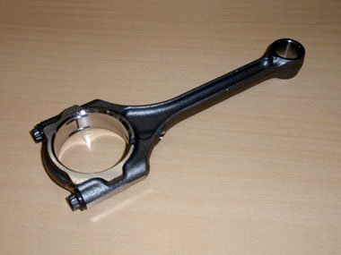
Connecting rods, also known as con rods, are important components for powering a vehicle. Connecting rods convert the vertical movement of a piston in a cylinder block into the rotary motion of a crankshaft. They should be light and strong, so they are typically made of chromium steel, chromium molybdenum steel, nickel chromium molybdenum steel, or a titanium alloy.
The part that connects to the crankshaft is called the big end. This part is divided into two units - the rod and the cap. The rod and the cap are connected by a con rod bolt. Each model has standard torque values for tightening these bolts as well as standard slit width values, a measurement of the space between the rod and cap, for the connected portion after tightening. These values help ensure that the rod and cap do not separate because of a loose bolt.
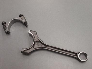
Cap (upper component) and rod (lower component)
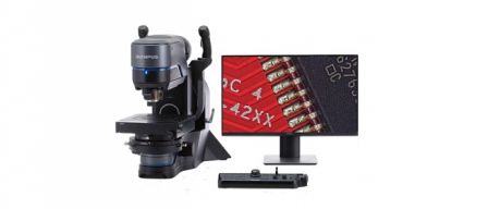
If the slit width is within the standard value, the connection is secure, and the rod and cap will not separate even if the crankshaft rotates intensely thousands of times per minute. However, a slit width that falls outside the standard value might mean that the cap and rod can potentially separate. For this reason, it is essential that the slit width is precisely measured during quality control to check for abnormalities. This measurement is performed at high precision with a microscope.
The Challenges of Measuring Slit Width Using a Conventional Microscope
It can be challenging to measure the slit width using a conventional microscope. For instance, if you’re zoomed to inspect a specific area of the slit width, you can’t see the entire slit because of the narrow field of view. On the other hand, if you are observing the entire slit at low magnification, it may be difficult to see details clearly due to the low lens resolution.
The DSX1000 digital microscope can overcome these common challenges and enable high-precision measurement of the con rod’s slit width.
Benefits of Measuring Slit Width Using the DSX1000 Digital Microscope
1) View the entire slit clearly at low magnification
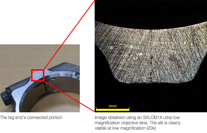
The DSX1000 digital microscope is equipped with a dedicated low-magnification, high-resolution objective lens that enables you to observe the rod’s entire slit. The ability to view the entire slit clearly makes it possible to set the appropriate point for measuring slit width.
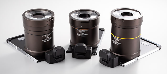
SXLOB ultra-long working distance objectives with low magnification
2) See a wide field of view (FOV) at high magnification
Using a high-magnification objective lens and the microscope’s image stitching function, you can quickly create a high-quality, wide field of view image suitable for precise slit width measurements. Paste multiple highly magnified images on the measurement area to create your image.

Pasted image of a magnified slit (140X).
You can immediately identify the point to measure
3) Automatically detect the slit edge of a connecting rod
If multiple operators manually measure the slit edge position, you risk taking inconsistent measurements. The DSX1000 digital microscope reduces variation with a function that automatically identifies the edge. This feature helps you maintain consistent measurement results regardless of who measures the slit width.
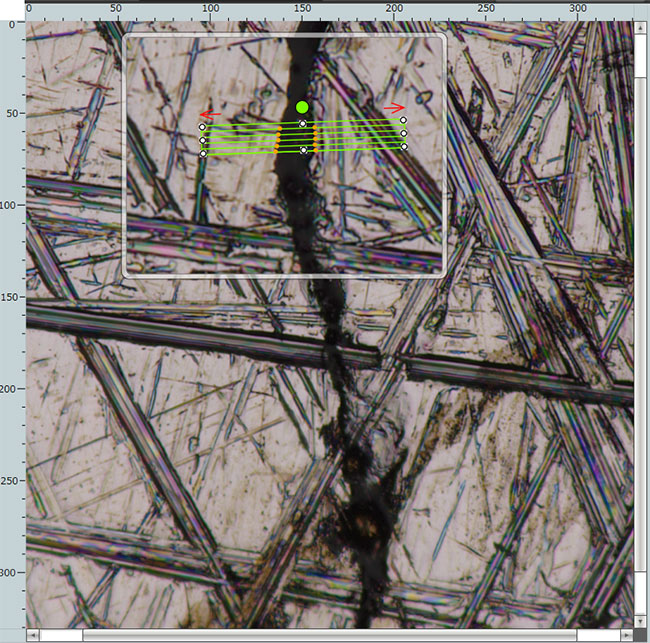
The edge auto-detection function instantly identifies the slit edge (700X)
In the image above, the auto-detection function automatically detects the slit edge in the green-framed area. Orange dots indicate the detected edges of both sides of the slit. The slit width of this area is the average value of the slit widths between the dots. You can also arbitrarily set the green frame width and length.