Precision Ultrasonic Gauging: Factors That Can Impact Testing
Quality ultrasonic thickness gauges can offer highly accurate testing on metals, plastics, and other materials. However, several factors related to the test material, equipment, part geometry, and user skill and care can affect the degree of accuracy achieved in an application. Read on to learn factors that can impact ultrasonic testing results.
Material-Related Factors
The physical properties of the test material is one factor that affects an ultrasonic thickness gauge’s measurement range and accuracy. This includes both acoustic and geometrical factors.
1. Acoustic Properties of the Test Material
Several conditions found in some engineering materials can limit the accuracy and range of ultrasonic thickness measurements:
- Sound scattering: In cast stainless steel, cast iron, fiberglass, and composite materials, sound energy will scatter from individual grain boundaries in castings or boundaries between fibers and matrix in the fiberglass or composite. Porosity in any material can have the same effect. Make sure to adjust the gauge sensitivity to prevent the detection of these spurious scatter echoes. This compensation can limit the gauge’s ability to detect a valid return echo from the back wall of the material, restricting the measurement range.
- Sound attenuation or absorption: In many polymers like low density plastics and in most types of rubber, sound energy is attenuated very rapidly at the frequencies used for ultrasonic gauging. This attenuation typically increases with temperature. The maximum thickness that can be measured in these materials is often limited by attenuation.
- Velocity variations: An ultrasonic thickness measurement is accurate only to the degree that the material sound velocity is consistent with the gauge's velocity calibration. Some materials exhibit major variations in sound velocity from point to point. This happens in some cast metals due to the changes in grain structure that result from varied cooling rates and the anisotropy of sound velocity with grain structure. Fiberglass can show localized velocity variations due to changes in the resin/fiber ratio. Many plastics and rubbers show a rapid change in sound velocity with temperature, requiring that operators perform the velocity calibration at the same temperature as the measurement.
- Phase reversal or phase distortion: The phase or polarity of a returning echo is determined by the relative acoustic impedance (density × velocity) of the boundary materials. Ultrasonic gauges assume the customary situation where the test piece is backed by air or a liquid, both of which have a lower acoustic impedance than metals, ceramics, or plastics. However, in some specialized cases, such as measurement of glass or plastic liners over metal, or copper cladding over steel, this impedance relationship is reversed and the echo appears phase reversed. To maintain accuracy in this situation, make sure to change the appropriate echo detection polarity. An even more complex situation can occur in anisotropic or in homogeneous materials, such as coarse-grain metal castings or certain composites, where material conditions result in multiple sound paths in the beam area. In these cases, phase distortion can create an echo that is neither positive nor negative. Carefully experiment with reference standards in these cases to determine the effects on measurement accuracy.
2. Physical Properties of the Test Material
The size, shape, and surface finish of the test piece must also be considered to establish the limits of measurement range and accuracy.
- Surface roughness of the test piece: The best measurement accuracy is obtained when both the front and back surfaces of the test piece are smooth. If the contact surface is rough, then the minimum thickness that can be measured will be increased because of sound reverberating in the increased thickness of the couplant layer. Inefficient coupling may reduce the echo amplitude. Also, if either the top or bottom surface of the test piece is rough, it can cause distortion in
the returning echo due to the slightly different multiple sound paths seen by the transducer, resulting in measurement inaccuracies.
For corrosion measurements, loose or flaking scale, rust, corrosion, or dirt on the outside surface of a test piece will interfere with the coupling of sound energy from the transducer into the test material. For this reason, clean any loose debris from the sample with a wire brush or file before measuring. Generally, performing corrosion measurements through thin layers of rust is possible as long as the rust is smooth and well bonded to the metal below. Keep in mind that some very roughcast or corroded surfaces might need to be filed or sanded smooth to ensure proper sound coupling. You may also need to remove paint if it is flaking off the metal.
- Curvature of the test piece: A related issue is the transducer alignment with the test piece. When measuring on curved surfaces, it is important to place the transducer around the centerline of the part and hold it as steadily as possible on the surface. A spring-loaded V-block holder can be helpful for maintaining this alignment. In general, as the radius of curvature decreases, the size of the transducer should be reduced, and transducer alignment becomes progressively more critical. For very small radii, an immersion approach with a focused transducer is required. In some cases, it helps to use a waveform display as an aid to maintain the best alignment. Also, on curved surfaces it is important to use only enough couplant to obtain a reading. Excess couplant will form a fillet between the transducer and the test surface where sound will reverberate and might create spurious signals that can trigger false readings.
- Taper or eccentricity: If the contact surface and back surfaces of the test piece are tapered, eccentric, or otherwise angled or misaligned with each other, the return echo will be reduced in amplitude and might be distorted due to the variation in sound path across the width of the beam, reducing the measurement accuracy. Typically, the measured thickness will represent an approximate integrated average of the changing thicknesses in the beam diameter. In cases of significant misalignment, measurement is impossible because the reflected beam will form a V-path away from the transducer and cannot be received. This effect becomes greater as the material thickness increases.
Operator-Related Factors
Calibration: The accuracy of any ultrasonic measurement is only as good as the accuracy and care taken during calibration. Make sure to perform the velocity and zero calibrations described in Section 4 when the test material or transducer is changed. We also recommend periodic checks with samples of known thickness to verify that the gauge is operating properly.
- Beam alignment: Always hold the transducer flat when testing on flat surfaces and normal to the radius of curvature when testing on curved surfaces. When testing on curved surfaces, always center the transducer on the curve. Misalignment will cause echo distortion, which will negatively affect the accuracy.
- Coupling technique: In Mode 1 measurements with contact transducers, the couplant layer thickness is part of the measurement and is compensated by a portion of the zero offset. To achieve maximum accuracy, the coupling technique must be consistent. For consistent measurements, use only enough couplant to achieve a stable reading and apply the transducer with uniform pressure. Practice will show the degree of moderate to firm pressure that produces repeatable readings. Also,
never scrape or drag transducers across rough surfaces. In general, smaller-diameter transducers require less coupling force to squeeze out the excess couplant than larger diameter transducers. In all modes, tilting the transducer distorts echoes and causes inaccurate readings.
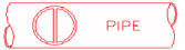
For corrosion gauging on small-diameter pipes and tubes, hold the transducer so that the sound barrier material visible on the probe face is aligned perpendicular to the center axis of the pipe, as shown below.
Equipment-Related Factors
While instrument design factors like digital sampling rate will set the limits of range and accuracy for an ultrasonic gauge, the range and accuracy in an application is ultimately determined by the combination of gauge, transducer, and setup, as well as material-related factors. For information on the typical materials and thickness ranges that can be measured with ultrasonic gauges using specific transducers and appropriate instrument setups, visit Section 9.0 Appendices – Transducer Range Charts.
Note that precision gauges using single element transducers typically have higher inherent accuracy than corrosion gauges using dual element transducers.