Introduction
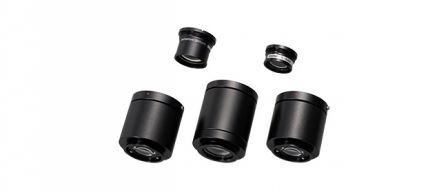
To support equipment and instrument designers, we supply an extensive range of objectives and other optical components to microscope-based imaging system manufacturers. These components help their engineers efficiently design high-quality optical inspection equipment.
One application that requires microscope-based imaging systems is semiconductor inspection. Semiconductor manufacturers require fast, accurate, and clean inspections throughout the manufacturing process. They rely on optical inspection equipment manufacturers to innovate inspection tools that keep up with the demands of the industry. Semiconductor manufacturers often source the opto-mechanical assemblies needed for semiconductor inspection to optical imaging experts. One essential component in this application is the optical system’s autofocus, which greatly influences the overall inspection speed. The autofocus is combined with the optical systems’ motorized Z-mechanism, illumination, microscope objectives, and a digital camera or sensor to complete the system.
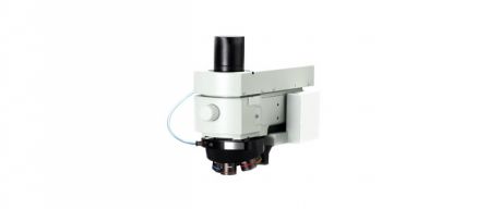
In this white paper, we explain how we created an automatic focus adjustment system (BXC-FSU) in combination with the microscope’s motorized Z mechanism, illuminator, lamp housing, objective lens, and other components to help semiconductor manufacturers complete the inspections quickly and efficiently.
What is autofocus?
There are two types of autofocus systems:
- Passive systems focus using the observed image. This technique is often called the image contrast method, however, it does not work on low-contrast specimens like bare wafers. Using this method, it is difficult to determine the focusing direction, so the Z-stage must be moved up and down to detect the increase or decrease in the specimen’s contrast. This slows down the focus speed and makes it difficult to keep track of the focus. However, this method has the advantage of being relatively inexpensive.
- Active systems irradiate light from a dedicated light source onto the specimen and focus based on the returned light. This technique is for advanced inspection systems where the specimen lacks contrast, such as flat panel and bare wafer inspection systems (Figure 1).
 | 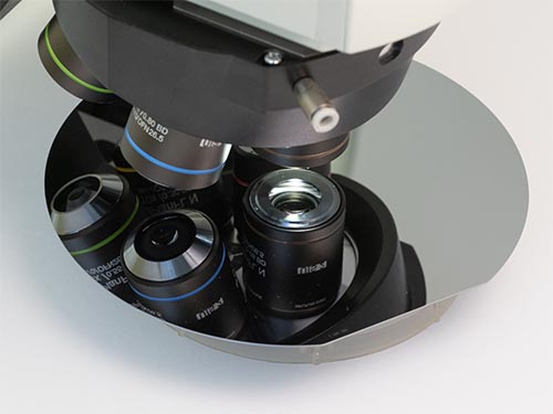 |
Figure 1. Bare wafer inspection.
Active split pupil method
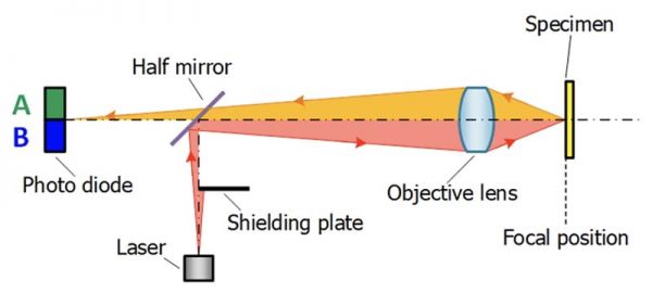
Figure 2. Outline of the active split pupil method.
One active method for focus sensing is pupil splitting (Figure 2). In this method, a shielding plate is placed between the light source and the lens (Figure 2). The light emitted from the laser source is blocked on one side by a shielding plate. After directing the laser light through the objective lens to the specimen, the laser light reflects from the specimen and enters the two-segmented photodiode by means of a half-mirror. The intensity of light entering each side (Figure 2 A and B) changes depending on whether the specimen is on the far or near side of the focus. The autofocus unit senses the current flowing through A and B and converts this into the ‘error signal’ using the equation (A-B)/(A+B). The in-focus position is the Z position where the intensity of light incident on both sides of the photodiode are equal. In other words, when the error signal is approximately equal to zero, the autofocus unit knows the specimen is in focus.
Figure 3 illustrates how the signals incident on the A and B sides of the two-segmented photodiode and the error signal values change depending on the specimen position.
Figure 3. Focus sensing with the active split pupil method
Focus error signal output
The autofocus unit control box receives the signal and transfers it to the software that is driving the motorized Z movement. To output the focus information to the customer's device, the BXC-FSU is combined with the BXC-CBB controller (Figure 4).
See how the BXC-CBB system works
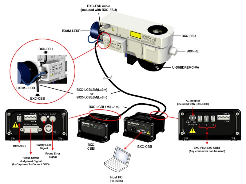
Figure 4. Configuration of the BXC-CBB system.
The focus information travels through the system in the following way: BXC-FSU→BXC-RLI→BXC-CBB→BXC-CBE1. The BXC-CBE1 controller creates the analog signal that is transferred to the customer's equipment based on the focus information originally provided by the BXC-FSU.
There are three types of focus signals produced by the BXC-CBE1:
- Focus error signal
- In-capture signal
- In-focus signal
The (A-B)/(A+B) error signal described above is output as an analog signal ranging from -10 V to +10 V, and the direction of the focus position can be determined by whether the voltage is positive or negative.
The position where the error signal crosses 0 V is the in-focus position. As shown in Figure 5 the in-focus signal activates when the error signal is within the in-focus threshold range around 0 V. The range in which the in-focus signal activates is defined as the range in which the specimen is within the depth of focus of the objective lens (in focus).
However, as shown in the red boxes in Figure 5, the error signal is also 0 V when the specimen is far from the in-focus position. This happens because the intensity of laser light reflected from the specimen and incident on the two-segment photodiode lowers the further the specimen is from the in-focus position. The in-focus signal is indicated to be active when it is actually low in Figure 5.
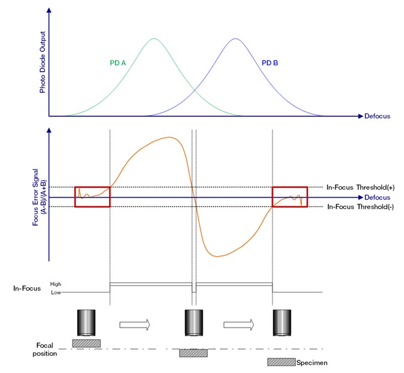
Figure 5. The change in error signal (A-B)/(A+B) and in-focus signal at each Z position.
The in-capture signal indicates the intensity of the laser light emitted from the autofocus unit and reflected from the specimen to the photodiode. Because the system can recognize the intensity, it can tell whether the zero signal is caused by low intensity and the sample is not actually in focus. This in-capture signal occurs when the specimen is located near or close to the focus position and is called the in-capture range. When the specimen is within the in-capture range, the autofocus can be activated and used to achieve actual focus. Whether the specimen is within the in-capture range is determined when the total amount of light (A+B) incident on the two split photodiodes exceeds a certain threshold value (Figure 6).
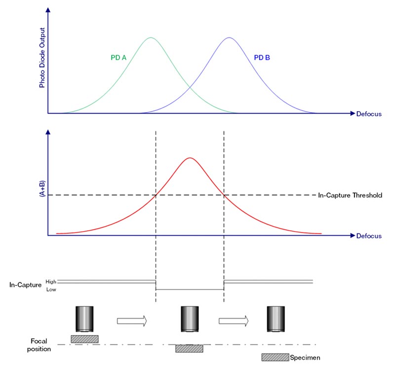
Figure 6. Variation of total light intensity A+B and the in-capture signal at each Z position. The in-capture signal activates when A+B exceeds a certain threshold value. The in-capture signal is indicated to be active at low in this figure.
To summarize, the in-focus position is the range where the in-capture signal output from the BXC-CBE1 is active, the error signal is near 0 V, and the in-focus signal is also active. Figure 7 below shows the status of the in-capture and in-focus signals at each Z position. Here, the in-capture and in-focus signals are active at low.
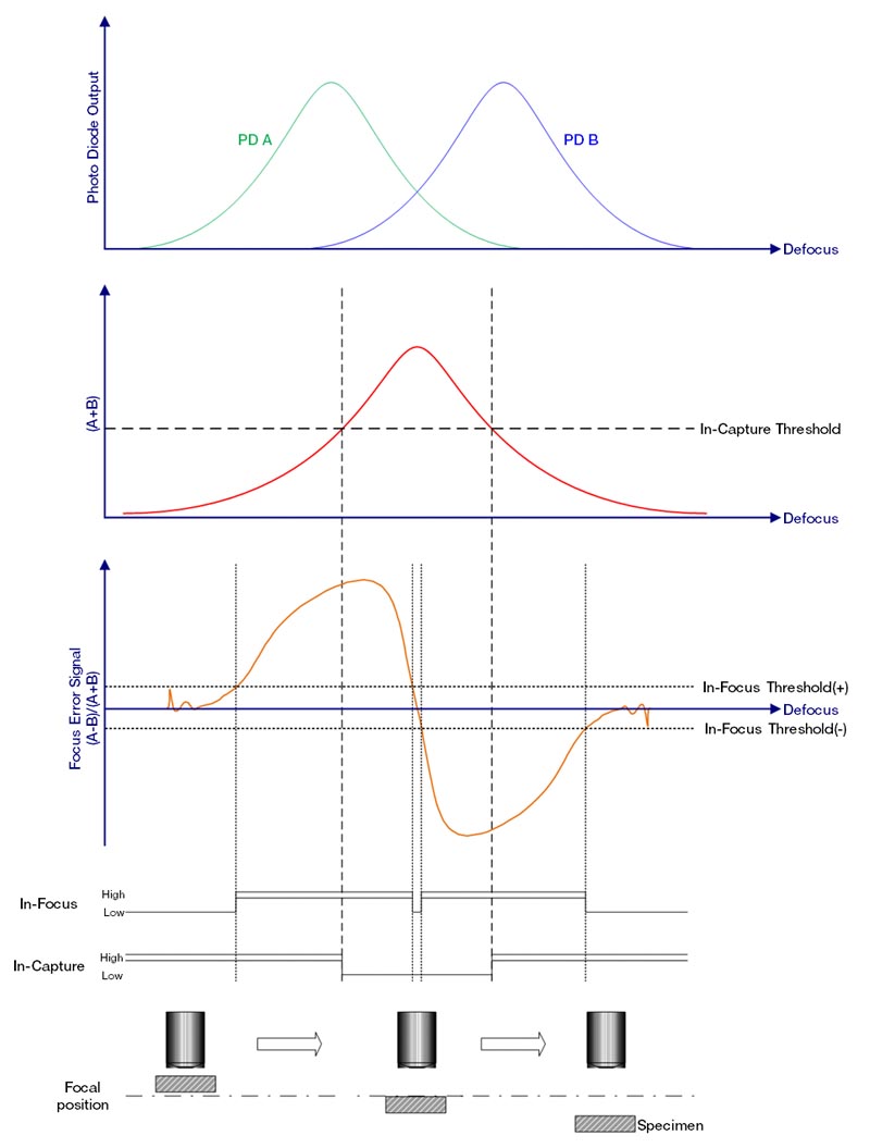
Figure 7 . Changes in the in-capture and in-focus signals.
Based on the above, monitoring the three signals output from the BXC-CBE1—the error signal, the in-capture signal, and the in-focus signal—makes it possible to find the focus and communicate with the customer’s selected Z motor and Z drive. These are all actively working in coordination as the stages moves to each inspection location (Figure 8).
Figure 8. The relationship between the objective lens, live image, and waveform (oscilloscope signals; error signal: green; in-focus: yellow; in-capture: blue).
An oscilloscope can confirm that all signals are active when the image is in focus. This can be used in the design and development of the instrument.
Multispot laser projection
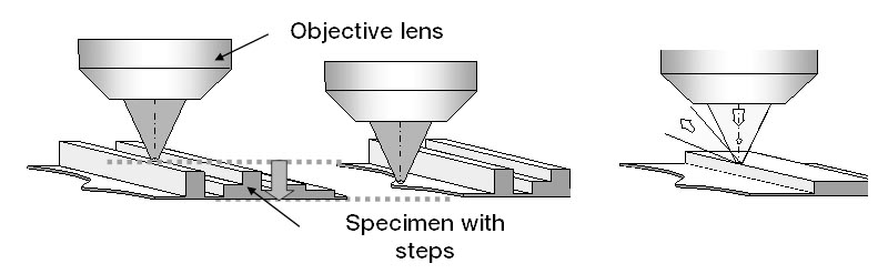
The specimen’s topography can affect the success of achieving focus. When a laser is projected onto a specimen at a single point and the specimen has a step structure, such as fine wire patterns on semiconductor substrates, the in-focus position can frequently change as the specimen is scanned. This is known as chatter. It is also possible to see the deterioration of the signal-to-noise ratio (SNR) of the focus error signals due to the scattering of AF light at the edge of the step (Figure 9). Both situations make it hard to maintain focus throughout the inspection and slows it down.
To reduce chatter and improve focus stability, the BXC-FSU employs a multispot active autofocus system (Figures 10 and 11). The spots are arranged in a 45-degree angle across the field of view, and the average signal from all the spots produces an average in-focus position. Averaging the focus over the field of view makes it possible to reproducibly autofocus when the specimen has varying heights within the field of view.
(a) Variation in focus position (b) Scattering by edges
Figure 9 . Focus instability factors.

(a) Single-spot method (b) Multispot method
Figure 10. Comparison of focal spots on the specimen surface.
(a) In the single-spot method, when shifting the specimen to the side where there is a step height significantly moves the Z position, causing the image to go out of focus.
(b) Using the multispot method, the focus position does not change even if there is a step height on the specimen and it translates laterally.
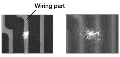
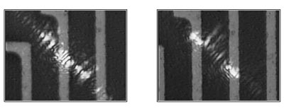
Figure 11. Comparison of focus stability between the one-shot and multispot autofocus detection methods with specimens with step heights. Bright dots indicate the in-focus detection points.
Chromatic Aberration Correction
Because the BXC-FSU autofocus unit uses a near-infrared laser light source, the stage position for focus is different for the laser and white light source. This is due to chromatic aberration where the refractive index of the glass used in the lens differs depending on the wavelength of light (Figure 12). For this reason, the BXC-FSU is equipped with a mechanism to correct chromatic aberration and match the focus position of visible light and infrared laser light. Chromatic aberration is corrected each time the objective is switched by the nosepiece based on a predefined amount assigned in the software.
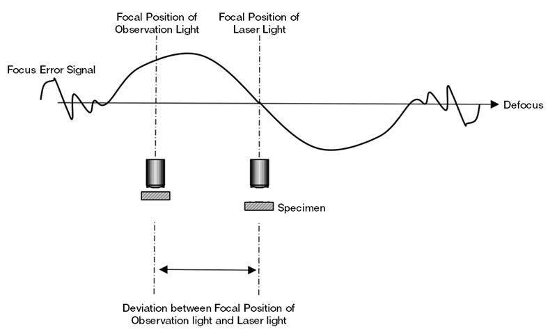
Figure 12 . Chromatic aberration in the objective lens results in two focus positions for visible light and laser light.
Conclusion
Autofocus technology maximizes scan times and resolution accuracy. Understanding the principles of focus sensing will help you get the most out of the BXC-FSU and incorporate it into your device.
To evaluate whether this device will work in your product, please visit the resources page to find additional documents.
To help you understand the command control of the BXC-CBB and BXC-CBRLM systems, you can download sample software and try it for yourself.
The BXC-FSU application manual, which explains how to use the FSU, is also available.
To obtain a copy, please fill out an inquiry form and write “Request for Application Manual” in the comments section.