Inspection & Measurement Systems

Falvastagságmérők

35 Sorozat

35 Series

The pocket-sized 35 series is a handheld ultrasonic thickness gage for precision measurements on metal, plastic, rubber, glass, and composites using single element transducers. Wide thickness range from 0.08 mm to 635.0 mm (0.0030 in. to 25.0 in.) Optional live Waveform and Adjust Mode.

Panametrics 35 Series Features

• Velocity and Reduction Rate measurements are standard on all models
• Wide thickness range from 0.08 mm to 635.0 mm (0.0030 in. to 25.0 in.) depending on instrument and material
• Uses contact, delay line, and immersion transducers
• Application Auto-Recall with default and custom setups
• Hand-held; weighs only 0.24 kg (8.5 oz)
• Min/Max Mode
• Hi-Low alarm
• English and metric display (inches/mm)
• Multi-language user interface
• Long battery life

Panametrics 35 and 35DL

35 and 35DL are used in the majority of applications
The 35 and 35DL can use transducers ranging from 2.25 to 30 MHz, which means that these versatile gages can solve the majority of thickness gaging applications, from very thin to very thick. In general, transducers with higher frequencies and smaller diameters allow measurements of thinner or curved parts and enhance the accuracy of the measurement.

Applications
• most materials, from thin to thick
• plastic bottles, tubes, pipes, sheets as thin as 0.08 mm (or 0.003 inch)
• metal containers, steel coils, machined parts as thin as 0.10 mm (or 0.004 inch)
• cylinder bores, turbine blades
• glass bulbs, bottles
• thin fiberglass, rubber, ceramics, and composite materials
• curved areas or containers with small radii
• resolution up to 0.001 mm or 0.0001 in.

Models 35HP and 35DL-HP

With a very low ultrasonic frequency bandwidth and a special pulser-receiver, the HP gages are specifically designed to optimize ultrasound penetration when measuring thick, highly sound attenuating or sound scattering materials. Typically these materials cannot be measured with most other ultrasonic thickness gages.

Applications
• most thick or sound-attenuating materials
• thick cast metal parts
• thick rubber tires, belts
• fiberglass boat hulls, storage tanks
• composite panels
• resolution of 0.01 mm or 0.001 in.

The 35HP gages are excellent tools to measure fiberglass or composite parts, from aerospace structures to boat hulls and storage tanks that require thickness control.

Why HP gages
For more than three decades, we have developed the HP (High Penetration) series specifically for very sound-attenuating or thick materials. Not only can these gages use transducers as low as 0.5 MHz but their electronics (pulser-receiver) are highly optimized to process signals at these low frequencies. The result is that the Panametrics-NDT gages have earned a reputation for superior performance in measuring thick rubber, fiberglass, composites, and other tough materials.

Other Panametrics 35 Series Features

With reduction rate you can measure critical thickness metal thinning caused by bending.


Reduction Rate Measurements
Differential Mode and Reduction Rate Mode are standard features on all models. Differential Mode shows the thickness variation from a pre-set thickness value. Reduction Rate calculates and displays the percent of thickness reduction after a material thinning process. A typical application is automotive sheet steel that is bent and formed to make car body panels.

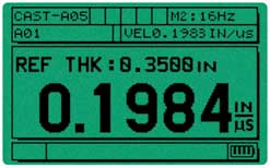
Velocity measurement mode with direct Velocity readout.

Material Sound Velocity Measurements
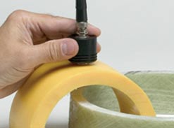
All Panametrics 35 models have the capability to make material sound velocity measurements. This standard feature is useful in applications where the speed of the sound within the material can be correlated to other properties. Typical applications include cast metals to monitor the degree of nodularity, and composites/fiberglass to monitor variations in density. Olympus offers a digital caliper for automatic transfer of measurement thickness.

Application Auto-Recall Simplifies Gaging
Application Auto-Recall simplifies making thickness measurements. Select any of the stored transducers and the 35 gages recall all relevant internal transducer parameters.
Stored Standard SetupsStandard setups include most commonly used transducers.
Stored Custom SetupsJust in case your special application problem cannot be solved with a Standard Setup, these gages can create, store, and recall as many as 20 Custom Setups (10 with the 35 and 35HP).

Micrometers won't work in this classic application. Instead, the Model 35 with a M208 transducer makes a thickness measurement up to a calibrated accuracy of 0.001 mm (or 0.0001 inch) without breaking the glass .

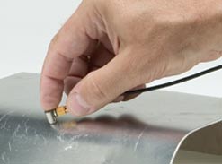
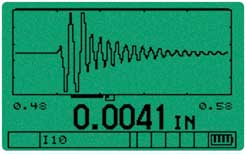
Thickness and waveform of a very thin (0.10 mm or 0.004 in.) sheet of steel.

Why ultrasonics?

Ultrasonic measurements are accurate, reliable, and repeatable. Instant digital readings can be achieved by transmitting sound into just one side of a material, making it unnecessary to cut or destroy parts where the opposite side is difficult to reach and where micrometers or other inspection tools cannot do the job.

35, 35DL, 35HP and 35DL-HP Specifications*

Measurements
Mode 1: Time interval between excitation pulse and first back wall echo, using contact transducers.
Mode 2: Time interval between the first interface echo after the excitation pulse and the first backwall echo, using delay line or immersion transducers.
Mode 3: Time interval between successive back wall echoes following the first interface echo after the excitation pulse, using delay line and immersion transducers.

Measurement Types:
Thickness, Velocity, or Time of Flight
Thickness Measurement Range*: 0.08 mm to 635 mm (0.003 in. to 25 in.)
*Thickness range depends on model, material, transducer, surface condition, and setup selected.

Material Velocity Range: 0.5080 mm/µs to 18.699 mm/µs
(0.02000 inch/µs to 0.7362 inch/µs)
Resolution (keypad selectable):
LOW: 0.1 mm (0.01 in.)
STANDARD: 0.01 mm (0.001 in.)
HIGH: 0.001 mm (0.0001 in.)
(35 & 35DL)

Time of Flight Measurement Range: 0.0 µs to109.5 µs

Time of Flight Resolution: Fixed at 000.01 µs

Measurement Update Rate: 4, 8, 16, or Max Hz (16-20 Hz depending on application and measurement mode)

Transducer Frequency Range: 2.25 MHz to 30 MHz (35 & 35DL)
0.5 MHz to 5.0 MHz (35HP & 35DL-HP)

Min/Max Mode: Displays current thickness, minimum or maximum thickness depending on setting.

Display Hold/Blank: Displays blanks after last reading or holds reading.
Alarm Mode:Programmable Hi-Low alarm set points with audible and visual indicators

Differential Mode: Displays thickness difference between actual measurement and reference value.

Reduction Rate Mode: Displays thickness and percent difference between actual measurement and reference value.

Application Auto-Recall: Automatically adjusts internal parameters for various default and custom transducer setups.

# of Default# of Custom
35 21 10
35DL 21 20
35HP 17 10
35DL-HP 17 20

Other Standard Features: Calibration Lock Mode, Internal Diagnostic Test Mode, Metric/English Units, On-board Statistics (35DL and 35DL-HP only)

POWER SUPPLY
Battery: 3 AA alkaline or NiMH batteries
Operating Time: 150 hours typical battery life; 30 hours continuous with backlight on
Low Battery Indicator: Continuously indicates battery status.
Battery Saver: Auto Power Off/Continuous On
AC Power Supply: Optional

GENERAL
Environmental IP-65 compliant: Splash-proof, impact-resistant case. Sealed, color-coded keypad with tactile and audible feedback.
Operating Temperature Range:
-10° C to +50° C (+14° F to 122° F)
Size: (W x H x D)
84 mm x 152 mm x 39.6 mm
(3.31 in. x 6.0 in. x 1.50 in.)
Weight: 0.24 kg (8.5 oz)
Custom Language Utility: Allows translation of display text in many languages.

35DL & 35DL-HP
INTERNAL DATA LOGGER

Data Logger: The 35DL & 35DL-HP identify, store, recall, clear, and transmit thickness readings and transducer setup information via the USB port or optional RS-232.
Max. # of Stored Values: Over 31,000 or 1,300 waveforms with thickness readings (with Waveform Option)
Stored Data Documentation: Each saved thickness reading is fully documented with measurement status flags and a setup number that identifies parameters such as velocity, transducer, etc.
File Name Length: 8 alphanumeric characters
Identification Codes: 10 character alphanumeric Identification Code system identifies or locates stored data
4 File Templates: Incremental, Sequential and 2D Grid. Manual files from PC.

STANDARD INCLUSIONS
Wrist Strap, 3 AA Batteries, Test Block, Transducer Cable, Couplant, Carrying Case, Instruction Manual, Two-Year Limited Warranty

OPTIONAL ACCESSORIES
35/WF Live Waveform
Gageview Interface Program
35DL/RS232 RS-232 output
35DLHP/RS232 RS-232 output
35PCScope PCScope Program
USB/ADP-115 AC-115 Power Supply
USB/ADP-230 AC-230 Power Supply
MG2/RPC Protective Rubber Boot
35/DLRETRO Upgrade 35 to 35DL
35HP/DLRETRO Upgrade 35HP to 35DL-HP

Software Options

35PCSCOPE

Optional 35PCSCOPE interface software permits the instant display of live ultrasonic waveforms and thickness readings directly on your computer screen. This is helpful when setup parameters require closer examination.

A-scan Mode: Now You Can See The Live Waveform And Make Adjustments 

Operator can view thickness and waveform with the optional A-scan mode

An optional Live Waveform Mode on all models permits the user to view the ultrasound waveform (or A-scan) directly on the gage's display to make sure the thickness reading is correct. The Adjust Mode feature facilitates transducer setup adjustments to maximize measurement performance for challenging applications.
• High pixel density LCD renders sharp trace of live waveform
• Permits real-time verification of thickness readings
• Helps solve many difficult applications
• A Range, Delay, or Zoom allow enlarging and centering to any section of the waveform
• Permits adjustments of transducer setup parameters
• Stores waveforms in data logger and transfers to PC

GageView

The GageView and GageView Pro Interface Programs are Windows-based applications that collect, create, manage, and print data from Olympus thickness gages and flaw detectors.

GageView is compatible with gage models 35DL, 35DLHP, and MG2-DL. It provides the following capabilities:

  • Creating Datasets and Surveys
  • Editing stored data such as thickness data
  • Viewing Dataset and Survey file information including thickness readings, waveform, gage setup values, and transducer setup values
  • Downloading and uploading thickness surveys to and from the Panametrics ultrasonic thickness gages
  • Exporting Surveys to spreadsheets and other programs
  • Collecting snapshot screens (graphical data sent by a thickness gage that duplicates the exact screen display)
  • Printing reports such as Thickness, Setup Table, Statistics, Color Grid, and others
  • Upgrading gage operating software

GageView Pro is compatible with flaw detector models Epoch 4, Epoch 4B, Epoch LT, Epoch 4 PLUS, and Epoch XT, as well as the gage models listed above. When used with flaw detectors, GageView Pro provides the following capabilities:

  • Exporting thickness or amplitude data saved on the Epoch to Excel, Word, or similar programs
  • Create, format, and manage test databases
  • Export real-time screen snapshots, including B-scans, to a PC or printer
  • Import and export setups between the Epoch and a PC
  • Set up inspection plan templates, including pre-loaded probe calibrations, IDs, and memos
  • Create a custom DGS probe library
  • Upgrade Epoch operating software

Olympus NDT offers a complete selection of transducers, cables, couplants, calibration test blocks, and accessories to meet a wide variety of ultrasonic precision thickness gaging applications.

Microscan transducer part numbers reflect the connector designation:
RM = Right Angle Microdot®
SM = Straight Microdot
RB = Right Angle BNC
SB = Straight BNC
SU = Straight UHF

When selecting a transducer, please review the chart below or consult the Transducer Frequency Range in the Instruction Manual that was shipped with your gage.

Thickness Gage Model Transducer Frequency Range

35, 35DL
25, 25DL
25DL PLUS
25MULTI PLUS

2.0 to 30 MHz

35HP, 35DL-HP
25HP PLUS
25HPV

0.5 to 5.0 MHz

Precision Thickness Gage Transducers

Loading...

Thickness Gage Tutorial

This self-guided web tutorial provides an introduction to the theory and practice of ultrasonic thickness gaging.

Review Now>>


English | 日本語 | français | 简体中文 | Deutsch | italiano | čeština | magyar | Tiểng Việt | Español | русский | polski | português | 한국어