OmniScan MX ECA/ECT

Please note that product availability varies by region. Contact your local Olympus sales office for more information.
- Overview
- Specifications
- Bond Testing
- Eddy Current Array Software
- Eddy Current Software
- Applications
- Resources
Overview
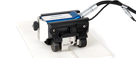
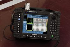
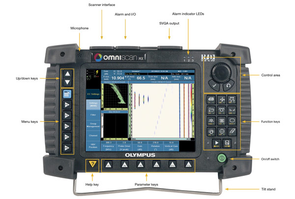
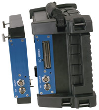
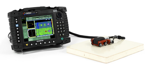
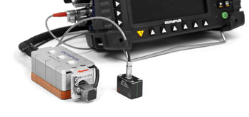
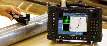
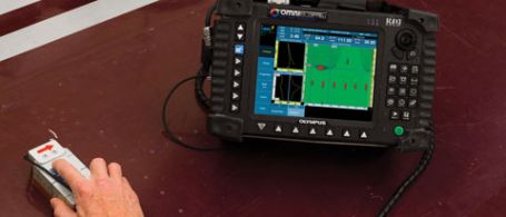
 The OmniScan MX
A Field-Proven, Dependable Instrument
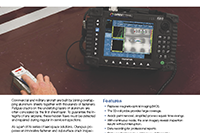
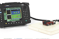
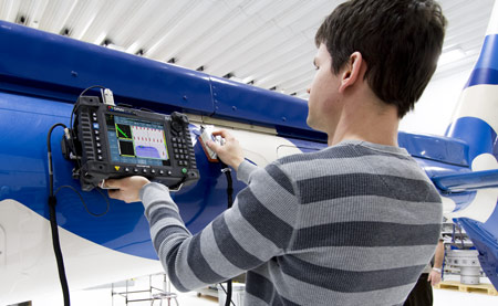
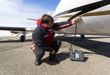
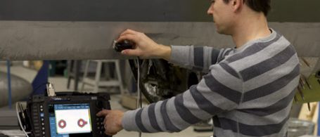
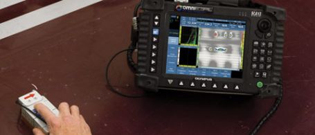
With thousands of units being used throughout the world, the OmniScan® MX is a field-proven, reliable instrument that is built to withstand harsh and demanding inspection conditions. Compact and lightweight, its two Li-ion batteries provide up to 6 hours of manual or semi-automated inspection time.
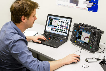
The highly legible 8.4 in. (213 mm) real-time color display of the OmniScan MX enables you to see defects and details under any light conditions. Navigate your way through the instrument’s simple and intuitive interface using the scroll knob and function keys, or by connecting a USB mouse to facilitate the inspection analysis.
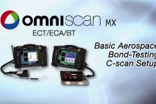
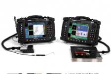
One Platform, Two Modules, Three Technologies: More Flexibility
To meet the requirements of a broader range of applications, eddy current testing (ECT), eddy current array (ECA) and the new bond testing (BT) C-scan technology are available in two module versions. Both of these modules are compatible with the MXE (ECT/ECA) and MXB (BT C-scan) software, providing easy transition between technologies and a very short learning curve.
 |  |  | ||
 | Conventional ECT | Eddy Current Array | Bond Testing C-Scan | |
ECT4 module | √ | Not supported | √ | |
ECA4-32 module | √ | √ | √ | |
Most Nortec probes supported | Supports 32 onboard channels and 64 channels with external multiplexer | Requires special adaptor and scanner |
ECA is just like ECT
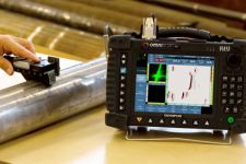
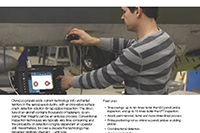
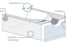
Large Coverage, Fast Scanning, and Higher Probability of Detection
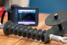
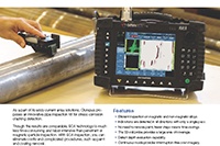
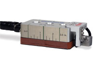
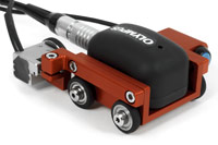
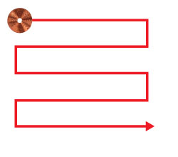
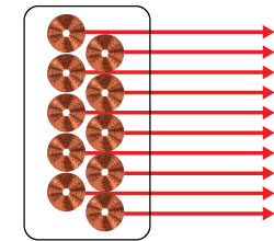
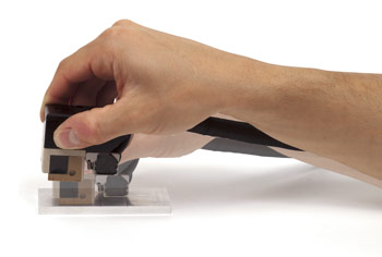
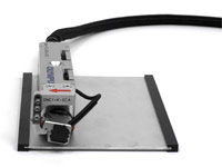
Eddy current array (ECA) technology incorporates several traditional bridge or reflection (driver-pickup) probe coils in order to achieve a much larger coverage in a single inspection pass. Additionally, each ECA probe model is carefully designed to maintain a high probability of detection of a targeted defect range, all along the probe length. With the OmniScan® MX ECA, you can use ECA probes at fast manual-inspection speeds, offering a powerful and productive inspection with color
representation and archiving capability.
Single coil: raster scanning |
Array probe: one-line scanning |
Inspection through Thin Coatings
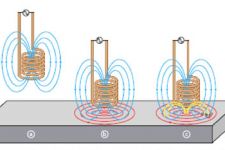
Eddy current testing (ECT) technology works on the principle of magnetic coupling of a probe sensor (coil) close to a test specimen (conductive material, ferromagnetic or non-ferromagnetic), generating eddy currents inside the test specimen, and displaying signals on the instrument’s impedance plane. With eddy current technology, you can detect defects through thin coatings (such as paint), as long as the distance from the probe to the metal is kept reasonably low—typically in the order of 0.5 mm to 2.0 mm.
As eddy current array and ECT technology share the same basic principles (and physics), it can also perform inspections through paint while offering all advantages of ECA, including large coverage, fast scanning, high probability of detection and color imaging.
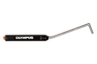
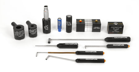
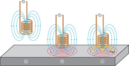 | Probes used to perform eddy current inspections are made with a copper wire wound to form a coil. The coil shape can vary to better suit specific applications.
|
Specifications
|
OmniScan MX > Overall dimensions
(W x H x D) | 321 mm x 209 mm x 125 mm (12.6 in. x 8.2 in. x 5.0 in.) |
|---|---|
| OmniScan MX > Weight | 4.6 kg (10.1 lb), including module and one battery |
| OmniScan MX > Display | 21 cm (8.4 in.) TFT LCD Display, 800 pixels x 600 pixels, 16 million colors |
| OmniScan MX > Power supply | Smart Li-ion batteries (up to 2), and DC-in voltage 15 V to 18 V (min. 50 W) |
| OmniScan MX > Battery Life | Minimum 6 hours with two batteries; minimum 3 hours per battery under normal operating conditions |
| OmniScan MX > Data storage | CompactFlash card, most standard USB storage devices, or through fast Ethernet, internal 32-MB DiskOnChip |
| OmniScan MX > I/O ports | 3 USB ports, Video output Video out (SVGA), Ethernet 10/100 Mbps, 2-axis encoders, 4 digital inputs (TTL). |
| OmniScan MX > Operating temperature range | 0 °C to 40 °C; 0 °C to 35 ºC with 32:128 PA (32 ºF to 104 ºF; 32 ºF to 95 ºF with 32:128 PA) |
| OmniScan MX > Storage temperature range | –20 °C to 70 °C (–4 ºF to 158 ºF) Relative humidity 0 % to 95 % noncondensing. No air intake; splashproof design. |
| MX Module Compatibility > OMNI-M-ECT4 | Supports conventional eddy current and bond testing C-scan (adaptors not included) |
| MX Module Compatibility > OMNI-M-ECA4-32 | Supports eddy current arrays, conventional eddy current, and bond testing C-scan (adaptors not included) |
| ECT/BT and ECA modules > Connectors | BNC Absolute Probe (ECT), 4-channel Universal Fischer 19 pins (ECT and BT), and OmniScan connector for ECA probes |
| ECT/BT and ECA modules > Number of channels | 1 to 4 (ECT); 32 (ECA), expandable up to 64 with external multiplexer; 1 (BT) with adaptor |
| ECT/BT and ECA modules > Probe compatibility |
Absolute, differential, bridge, reflection (driver-pickup) for both ECT and ECA probes.
Support select BondMaster pitch-catch probes through use of an adaptor (scanner also required). |
| ECT/BT and ECA modules > Probe recognition | Automatic probe recognition and setup for ECA and BT probes. |
| ECT/BT and ECA modules > Frequencies | 2 typical for most ECA and ECT setups or up to 8 on custom ECT applications or Bond Testing C-scan |
| ECT/BT and ECA modules > Operating frequency | 20 Hz to 6 MHz |
| ECT/BT and ECA modules > Maximum voltage | 12 Vp-p into 10 Ω |
| ECT/BT and ECA modules > Gain | ECT and ECA: 34 dB to 74 dB. BT: 28 dB to 68 dB. Additional adjustable software gain of 0 dB to 30 dB. |
| ECT/BT and ECA modules > Phase rotation | 0° to 360° with increments of 0.1° |
| ECT/BT and ECA modules > Acquisition (measurement) rate | 1 Hz to 15 kHz, variable depending on configurations. |
| ECT/BT and ECA modules > A/D resolution | 16 bits |
| ECT/BT and ECA modules > Filtering | FIR low-pass, FIR high-pass, FIR band-pass, FIR band-stop (adjustable cutoff frequency), median filter (variable from 2 points to 200 points), mean filter (variable from 2 points to 200 points) |
| ECT/BT and ECA modules > Channel processing | True automatic mixing, sensitivity normalization and encoder calibration |
| ECT/BT and ECA modules > Encoders | Time-based, one line scan or raster scan (2 axis) |
| ECT/BT and ECA modules > Alarms | 3 alarms, each configurable as Pie, Box, Ring/Circle. Alarm output as Visual, TTL and Sound. |
| ECT/BT and ECA modules > Analog outputs | Yes - one channel only. |
Bond Testing
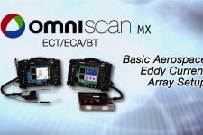
Eddy Current Array Software
Increased Power, Decreased Complexity
MXE 3.0 Software
With the exception of the added capacity to electronically switch between elements, eddy current array (ECA) technology is essentially the same as ECT technology. Eddy current array is easy to operate and calibrate. The new OmniScan MXE 3.0 ECA software has been redesigned to facilitate the transition from a conventional ECT instrument (such as the Olympus Nortec® 500) and to offer the power of ECA in a much more accessible way.
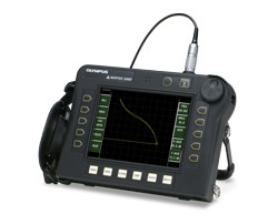 |  |
| Single channel ECT | 32 simultaneous channels |
 |  |
| Nortec 500 Main menu | OmniScan MXE 3.0 new Main menu |
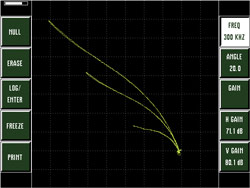
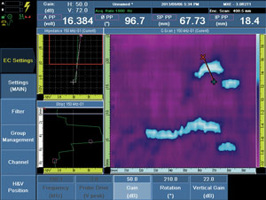
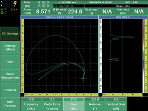
 Live Impedance Plane
Calibration of ECA is done in a nearly identical fashion as conventional ECT. The principles of lift-off, gain and null adjustments are maintained so calibration is no more complex or time-consuming than usual.
Generate live lift-Off signals with ECA probe – just like with a conventional ECT probe.
Adjust the phase angle in real time with the OmniScan knob. Gain, Vertical Gain and Null Point (H/V) can also be adjusted the same way.
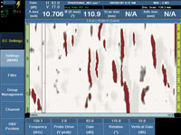
Replacement of Traditional NDT methods
Paint Removal is Obsolete
Eddy current array has a unique ability to perform inspections through thin coatings on conductive material. This capability provides a tremendous advantage over existing methods, such as penetrant testing, magnetic particle or magneto-optical imaging (MOI), as the need to remove and then reapply paint or coating is eliminated completely. Over time, this provides you with enormous cost-savings, and most importantly, your inspections will be chemical-free.
|
|
Part inspected with Penetrant Testing (visible red dye) | Scan using a standard ECA probe that features the same color representation as the red dye PT (patent rights protected). The sensitivity can be adjusted to reveal more or fewer defects. |

Key Advantages:
- No need for paint removal.
- Imaging and archiving.
- One-step inspection, high scan speed, and instant results.
- Major time-savings (typically 10:1 and over).
- Drastically reduced turnaround time.
- Defect depth evaluation capability.
- Adjustable sensitivity and post-process analysis.
- Environment-friendly method (no chemicals involved).
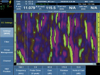
A Variety of Familiar Color-Palette Choices, Offering More Possibilities
The MXE 3.0 ECA software features a range of patent-rights-protected color-palette representations that replicate the look of traditional NDT methods and facilitate the intuitive display of ECA signals.
|
|
|
Penetrant Testing (fluorescent) | Magnetic Particle (red powder) | Magnetic Particle (fluorescent) |
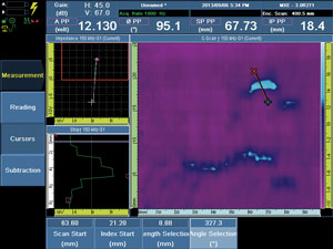
Analyzing, Reporting, and Archiving
Confirm or Revisit Inspections after Completion
Even after an in-field inspection has been completed, the OmniScan® MX ECA continues to provide value thanks to integrated data-storage, analysis, and reporting functionalities. With the OmniScan MX ECA you can review individual indications and apply corrections as needed. The new MXE 3.0 ECA software features newly redesigned, intuitive data cursors that can be operated directly from the instrument (on-site) or with a mouse connected by USB (office use).
|
|
New MXE 3.0 selection cursors are very intuitive and allow to quickly select any indication. | Corrections can be easily done on recorded data. Above example shows gain (contrast) adjustment. |
 Instant Reporting and Easy Archiving
The OmniScan MX features built-in reporting, at the touch of a key. Reports can also be configured and customized by advanced users. However, the factory-default report format already includes a screen shot and carefully selected, preloaded data fields that aim to eliminate the need for customization.
Archiving of inspection data files is also very easy; at any time (during acquisition or analysis), a single press of a key will instantly store the data on the instrument memory card.
Perform data analysis quickly and efficiently with mouse input. Archive files to a PC with the help of a CompactFlash reader.
Encoded Scans for Easier Data Interpretation
Optimized 1-2-3 Calibration
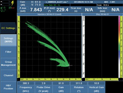
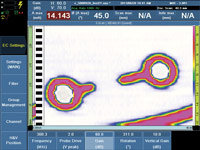
The OmniScan® MX ECA not only displays ECA signals in a conventional ECT impedance plane view but also offers several other views and layouts where the user will begin to recognize the true power of encoded ECA technology. These displays can be made part of the calibration workflow and can make eddy current testing highly visual and even go/no-go, based on user defined acceptance criteria.
Thanks to its intuitive interface design, the OmniScan MX ECA is quick and easy to configure and operate. It is as simple as one, two, three.
1 Adjust the usual ECT controls in real time using the live impedance plane. | 2 Activate the encoder and C-scan display. | 3 Fine-tune the settings and get ready to perform the inspection. |
|
|
|
Contrast adjustment using the gain in full C-scan display. |
 Continuous Encoder Mode
The advantage of time-based inspection is its virtually unlimited scanning capacity with minimal instrument interaction, whereas the benefit of encoded scans (C-scan images) is the ability to produce valuable color-coded images and information related to flaw position, shape, and dimensions.
The MXE 3.0 ECA software introduces a new Continuous Encoder mode that enables encoder-corrected imaging while maintaining the user-friendliness of a time-based inspection. With this mode, inspections are highly productive, with indications being recorded at your discretion.
Powerful Color Imaging
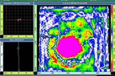
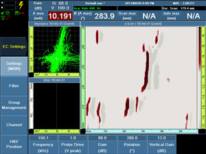
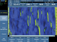
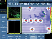
Estimation of Flaw Depth with Color-Coded C-Scans
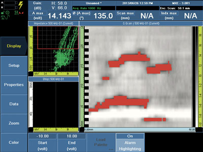
As with conventional eddy current technology, flaw severity is closely correlated to the return EC signal amplitude in most surface or near-surface applications. By using an amplitude-based color code, and plotting each channel’s return signal with encoded-position information, the resulting C-scan display is highly visual and intuitive. These scans can be saved to the removable CF card or generated into a report onboard the OmniScan® MX.
|
|
|
A reference standard with known depth defects is necessary to calibrate the sensitivity and contrast of ECA. | Image of a calibrated ECA scan showing different colors for each defect depth range. | Actual aircraft skin showing corrosion indications. The colors indicate the depth of the defects. |
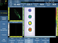
Accept or Reject Flaws Based on Threshold
With the OmniScan MX ECA, you can accept or reject indications based on the C-scan color display. The MXE 3.0 ECA software contains a wide range of factory-tested color palettes that optimize the signal display for any ECA application.
Additionally, the new C-scan alarm feature simplifies the gating of reject signals, as it instantly changes the C-scan colors when the impedance plane signal enters the alarm zones.
|
|
| |
A variety of application-specific color palettes come preloaded with the new MXE 3.0 ECA software | With the alarm feature, the C-scan changes color whenever a signal enters the reject zone. |

Eddy Current Software
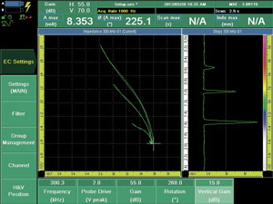
OmniScan MX in ECT Mode, a Powerful Flaw Detector
The Power of ECA and ECT combined
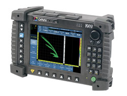
Some inspection procedures may specifically require ECT while ECA can easily help you cut time and find problem areas. With the OmniScan® MX ECA, you don’t need to commit to just one technology at the start of an inspection. Pressing and holding the menu key anytime during an inspection allows for instant switching between ECA and ECT modes. Both probes can remain connected and configuration setups remain active.
Simultaneous connection of ECA and ECT probes provides the best tool for the job without the need to stop and reconfigure your hardware setup
|
Press and hold menu key… |
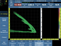
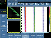
|
ECA interface (blue) is as easy to use as the ECT mode or a Nortec 500. | ECT interface (green) includes several features for procedure compatibility, such as adjustable null position. |
High Quality Signals, Existing Probes
The OmniScan MX in ECT mode includes a high quality signal digitizer and all-digital signal processing chain for minimal signal loss or distortion. This, combined with its bright, large display, makes the OmniScan MX in ECT mode one of the world’s finest ECT flaw detectors, displaying high-quality signals every time.
The OmniScan MX in ECT mode also allows the use of most existing Nortec® ECT probes, through the use of new cables and adaptors.
Applications
Stress Corrosion Cracking Solutions
Doubler Edge Skin Crack Inspection Solution
ECA Surface Crack Detection
ECA Subsurface Crack Detection

ECA Subsurface Corrosion Detection