In-Line ERW Tube Inspection System

Overview
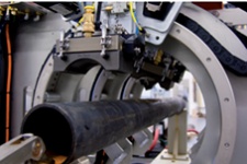
The in-line electrical resistance weld (ERW) tube inspection system is a turnkey solution that uses phased array technology integrated into a fully automated testing system to meet stringent inspection requirements. Key benefits include:
Designed to be an easy-to-use solution for helping ensure the quality of ERW tubes post welding, annealing, and sizing, the system includes:
| 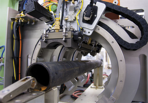 |
Profile and Track Welds while Detecting Flaws
A cylindrical phased array (PA) probe is located on each side of the tube’s weld to inspect in both clockwise and counterclockwise directions. To track welds and create a weld profile, a cylindrical PA probe located on the weld fires at zero degrees. Scarfing is automatically monitored, and the weld is profiled to create a side view for fast analysis.
- Wide coverage of the heat-affected zone (HAZ)
- Continuously monitor the weld profile and HAZ to perform analysis without waiting for the pipe to be cut
- Constant amplitude detection within the entire inspection area, even with mechanical movement
- Novel water wedge enables many degrees of freedom to accommodate pipe movement and provide excellent coupling
Automatic Weld Tracking
Our unique algorithm, based on time-of-flight analysis, automatically detects the scarfing area and sends feedback to the PLC to automatically adjust the inspection for each water wedge.
Fast Inspections, High-Quality Results
Our high-speed inspection systems are designed to meet the productivity requirements of the metal manufacturing industry. The systems adhere to the highest international quality standards, without compromising quality.
- Fire more than one acoustic configuration within the same PA probe—pitch-catch or high-angle pulse echo modes can be programmed to perform mid-wall inspection
- Small, automated gantry positions the inspection head in-line or off-line for inspections, automatic calibrations, or maintenance
- Available calibration bench to perform automatic calibration and calibration check sequences at standard inspection speed
Automatic Calibration
To achieve a thorough inspection, each PA probe must be calibrated. During calibration, the apertures of each probe pass over a known defect, and the probe’s gain level is automatically adjusted. This feature enables users to easily perform and validate a precise calibration of each focal law, saving time without relying on the user’s skill.
- Calibration check performed under normal production conditions
- Each reference defect is validated to help ensure they’re detected above the alarm level
- Results are displayed in easy-to-interpret views
Software and Acquisition Unit
Phased Array Acquisition Unit
The QuickScan™ PA 32:256 module meets IP55 standards and is designed to easily integrate into industrial environments.
Easy Setup
QuickView software makes it easy to set up the system and acquire and manage data.
The software’s wizard makes it simple to create setups for each part size. The inspection configuration and calibration parameters for each tube diameter are saved and easily retrievable. The final results are merged and displayed to clearly differentiate between accepted and rejected tubes.
- Quickly access predefined inspection setups
- Restrict access to certain users to help minimize operator errors
- Calibration and inspection information are stored for traceability
- System can be integrated within your inspection application, facilitating an operating mode that requires minimal human intervention
Specifications
| Product Range and Inspection Speed > Diameter | 60 mm to 245 mm (2.375 in. to 9.625 in.) |
|---|---|
| Product Range and Inspection Speed > Wall thickness | 3 mm to 16 mm |
| Product Range and Inspection Speed > Inspection speed | Up to 1.5 m/s (295 ft/m) |
| Inspection Coverage > Weld sector coverage | At least 25 mm for entire product range (adjustable) |
| Inspection Coverage > Axial pulse density (APD) | 1 mm (adjustable) |
| Inspection Coverage > Weld tracking capacity | -90º to +90º |
| Data Presentation > Real-time inspection result | C-scan, strip charts, and alarms |
| Data Presentation > Parameter setup | A-scan, B-scan |
| Data Presentation > Inspection layouts | 20 different user-configurable layouts |
| Inspection Modes* > Typical inspection modes |
45º, 60º, 70º (typical inspection configuration:
45º pulse-echo mode and 45º pitch-catch mode) |
| Inspection Modes* > Firing modes | Pulse-echo, pitch-catch |
| Inspection Modes* > Inspection mode configuration | Several inspection modes can be performed simultaneously on the same PA probe. |
| Detection Capabilities for Typical Reference Defects > API references |
1/2 in./1 in. (12.7 mm/25.4 mm) N10 and N5, ID and OD longitudinal notches
1/8 in. (3.2 mm) through drilled hole (TDH) 1/16 in. (1.6 mm) TDH |
| Detection Capabilities for Typical Reference Defects > Non-API references |
1/32 in (0.8 mm) TDH
1/8 in. (3.2 mm) half wall drilled hole 1/16 in. (1.6 mm) half wall drilled hole 1/32 in. (0.8 mm) half wall drilled hole |
| Detection Capabilities for Typical Reference Defects > Minimum SNR | 9 dB to 12 dB |
| Detection Capabilities for Typical Reference Defects > Repeatability |
LID/LOD notches: ≤ 1.5 dB
1/8 in. (3.2 mm) TDH : ≤ 2.0 dB 1/16 in. (1.6 mm) TDH : ≤ 2.5 dB |
| Reporting and Data Storage > Report types | Inspection, calibration, and calibration-check user-configurable reports |
| Reporting and Data Storage > Storage | Real-time database inspection data storage |
* The inspection modes mentioned are the most typical. Intermediate angles can be easily created with the Setup Wizard.