If you’re looking to integrate motorized components and controllers into a larger scientific instrument or device, it’s important to confirm their operation and control to verify that the unit works properly.
In this post, we introduce two easy ways to check the operation of embedded devices when considering your system integration.
As an example, we will discuss the versatile BXC-CBRML controller for our BXC series modular microscope assemblies. Featuring a manual illuminator and motorized revolver, this assembly is a good candidate for integration in semiconductor inspection equipment and a wide range of other imaging instruments.
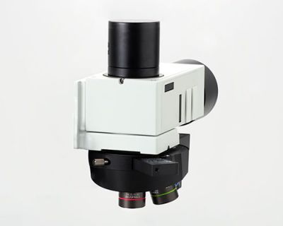
Figure 1. The BXC-CBRML versatile model with basic, compact assemblies integrates into a range of scientific instrumentation.
2 Simple Electric Control Methods for Microscope Assemblies
The BXC-CBRML unit can control a motorized revolving nosepiece, LED lighting, and MIX lighting. It operates using two control methods:
- Simple switchboard control via input/output (I/O): Recommended for single-function operations, such as moving a motorized revolving nosepiece in a smaller system. Operation via I/O from your circuitry is possible even without command control using a PC or other means. As a result, this method saves space and costs less.
- Command control via RS-232C: Recommended for complex operation sequences linked to the larger main instrument.
Here’s how you can easily confirm operation using these two methods:
1. Simple switchboard operation via I/O:
Let’s say you plan to operate an electric revolving nosepiece with a simple switchboard on the BXC-CBRML control box (Figure 2). It’s important to confirm the operation of the revolving nosepiece via the switchboard as a first step before integrating the device into your system.
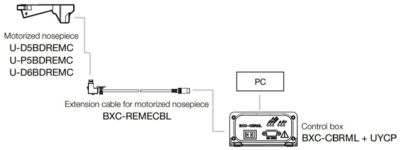
Figure 2. Simple combination of the electric revolving nosepiece and BXC-CBRML unit.
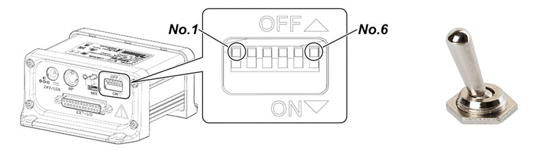
Figure 3. Create a switchboard by combining four pins with switch toggles.
To create a simple switchboard for the electric revolving nosepiece on the control box, use the bottom four pins of the 25-pin connector with commercially available toggle switches (Figure 3). This creates the four switches of SW0, SW1, SW2, and SW4. You also need to connect a 5 V power supply for the DC input.
The hole number (NP0 to NP2) where the revolving nosepiece moves to is specified by the on/off combination of the three switches of SW0 to SW2. When turned on, SW4 moves the revolving nosepiece to the specified hole position and stops. You can see these switch connections illustrated below in Figure 4.
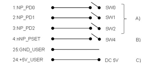
Figure 4. Example of a signal line and switch connections. A) Specify each hole position by configuring the three switches of SW0 to SW2 in the on or off position. B) SW4 moves the electric revolving nosepiece to the specified position. C) Supply 5 V power from an AC adapter to the DC input to power the unit.
As an example, Figure 5 below shows the configuration of the hole positions (NP0 to NP2) where the revolving nosepiece moves to using the binary digits (bits) of zeros and ones to signify off or on (0 = off, 1 = on).
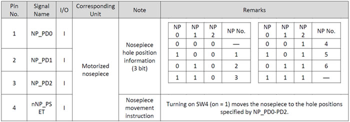
Figure 5. Position of the holes in the electric revolving nosepiece. The hole where the revolving nosepiece moves to is specified by the on/off combination of zeros and ones.
Using this method, the electric revolving nosepiece can be moved with four simple switches to any position simply by opening or grounding the pins corresponding to the 25-pin connector. No complicated circuitry is required.
Although a few more switches are required, almost all functions that can be controlled by BXC-CBRML commands can be operated in this same way.
The BXC-CBRML functions include:
- Revolving nosepiece position
- LED lighting: on/off and brightness adjustment
- MIX lighting: on/off and brightness adjustment
- MIX lighting: pattern setting and block selection
When you’re considering incorporating the BXC-CBRML unit into your equipment, please use this method as a simple operation test before preparing complex circuits and PLC programs.
2. Simulation of command control using sample software
All functions of the BXC-CBRML unit can be performed using command control via RS-232C, a common and simple interface (I/F) that‘s optimal for building a simple semi-automatic system.
We provide free sample software that lets you create command sequences in your software and simulate command sequences in action.
All you need is a PC, and no special installation work is required.
For this method, connect the D-Sub9 connector on the front of the BXC-CBRML unit to the PC with a straight RS-232C cable, as shown in Figure 6. Even a PC without an RS-232C port can be connected using a commercially available USB conversion cable.
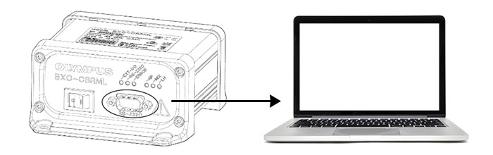
Figure 6. BXC-CBRML PC connection method.
Operations are performed on the screen shown in Figure 7. When you click on the button for each function, the command sequence required for that series of operations is displayed on the upper left screen. You can use this as a reference to build the sequence for your software. For details, please refer to the instructions that come with the sample software.
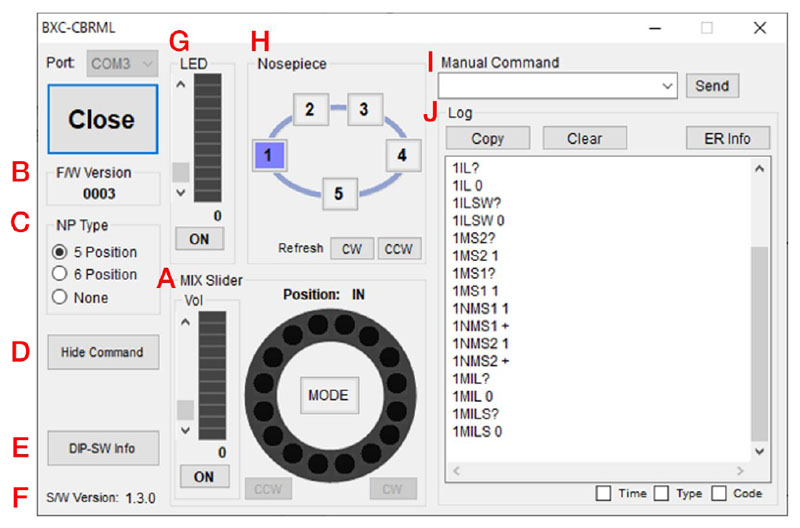
Figure 7. Example of the BXC-CBRML sample software showing command sequences. A) MIX slider operation area. B) Displays the firmware version read immediately after opening the common (COM) port. C) Displays the type of nosepiece read immediately after opening the COM port. D) Button to display or hide the command screen. E) Button to display the dual in-line package (DIP) switch information. F) Software version. G) LED lighting operation area. H) Nosepiece operation area. I) Manual
command operation area. J) Log display area.
Learn More about Integrating Microscope Components
When you’re looking to integrate microscope components into your equipment, these two methods let you verify operation immediately without the need to prepare special circuits or software. Depending on your application, a simple configuration with only a single function or control of complex sequences can be built in a flexible and compact microscope assembly. We hope you take advantage of it!
Please also refer to our related resources for integrating OEM microscope components. You can find detailed system configuration, an instruction manual, command specifications, CAD data, sample software, and an introductory video on our BXC series resource hub.