Built to meet IP66 and field proven, our rugged NORTEC™ 600 series flaw detectors can withstand harsh conditions. However, it underwent the ultimate in-field test earlier this year. Astronauts used the eddy current testing (ECT) device to inspect cracks on the International Space Station (ISS) and going into space is arguably the most extreme environmental test there is.
Finding and Repairing an Air Leak on the Space Station
The ISS is composed of many pressurized compartments and components that are connected and sealed at their joints. An accepted nominal air leak rate has been established and is monitored by ISS flight controllers. When a slight increase in the nominal leak rate of the ISS was detected, an investigation was launched. Although the increase was not considered hazardous to those on board, it could have long-term implications regarding compressed-air supply requirements. A supply that has to be transported in a rocket launched from Earth, so less is certainly better.
The source of the leak was identified as a small crack in the transfer chamber of the Zvezda service module. Essential elements of space station operation are contained in the service module:
- Living quarters
- Life support systems
- Electrical power distribution
- Data processing systems
- Flight control systems
- Propulsion systems
- Communication system
On pressurized containers, cracks can originate at many locations. In most cases, cracks begin at points with the highest stress loads, such as sharp edges, thick-to-thin transitions, and areas where repair has occurred.
The standard method for repairing cracks of this nature requires very precise marking of the crack tips. Olympus’ portable NORTEC 600D dual frequency model and a pencil-shaped probe were used since they would provide the required accuracy to determine the locations of the crack tips. NASA was able to certify the equipment for launch and for use on the ISS. Its user-friendly operation was relatively easy for the ISS crew to learn.
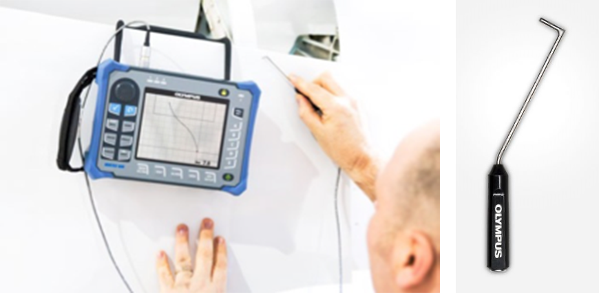
NORTEC eddy current flaw detector (left) and a bent-shaft probe (right) for surface crack detection
How Eddy Current Technology Works
Eddy current testing (ECT) uses electromagnetic induction to generate an oscillating magnetic field in conductive materials. For example, when an ECT probe is brought close to a metal part, a circular flow of electrons known as an eddy current will begin to move through the material like swirling water in a stream.
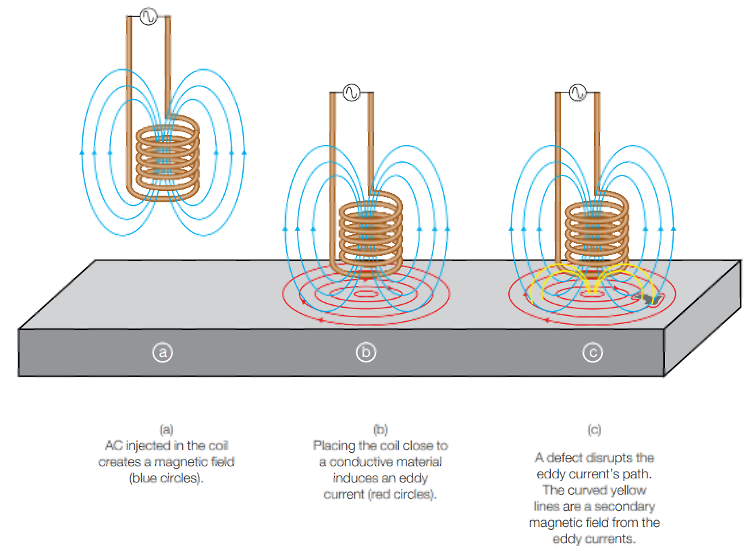
That eddy current flowing through the tested part in turn generates its own magnetic field, which interacts with the coil in the probe and its field through mutual inductance. Changes in metal thickness or defects such as near-surface cracking interrupt or alter the amplitude and pattern of the eddy current and the resulting magnetic field, varying the electrical impedance of the coil. The eddy current instrument plots changes in the impedance amplitude and phase angle, which can be used by a trained operator to identify changes in the part.
Detecting Crack Tips Using High-Frequency ECT Surface Probes
ECT probes normally used for surface crack detection, also known as high-frequency eddy current (HFEC) probes, have a small coil that can be made shielded or unshielded. It can be configured in four modes: absolute bridge, absolute reflection, differential bridge, or differential reflection.
To match the physical requirements, there are many types of surface probes, both in straight and angled versions. They are also available with flexible shafts that can be adjusted to different shapes. Surface probes can be designed with the sensitivity required to detect small crack tips. The size of the coil is selected to obtain good detection of the targeted crack length, depth, and width.
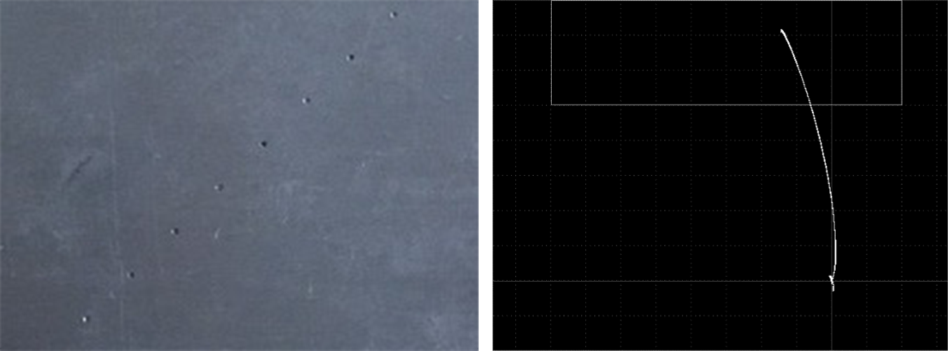
0.5 mm (0.020 in.) pin holes in a standard (left) and the signal amplitude results on of one pin hole (right) obtained with a probe with an absolute bridge coil configuration
Watch this tutorial video to learn how to configure the NORTEC 600 settings for surface and subsurface crack detection.
Meeting NASA’s Standards for Probability of Detection (POD)
To validate that the probability of detection (POD) complied with NASA’s requirements, a POD analysis needed to be conducted. To do this, a reference standard is scanned multiple times using the same inspection parameters and the results are recorded for analysis.
| Number of meas. | Number of successes | Number of failures |
|---|---|---|
| 29 | 29 | 0 |
| 46 | 45 | 1 |
| 61 | 59 | 2 |
The probability of missing a defect (p in the equation below) is calculated using the formula referenced in the standard used, such as this ISO equation:
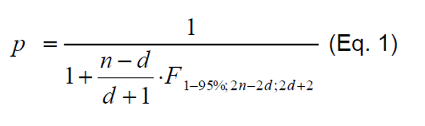
Where n is the number of inspections (hits plus misses), d is the number of misses, and F is the quantile of the F-distribution. When the NORTEC 600D flaw detector was tested, it demonstrated the required 90% POD of the targeted defects with a confidence level of 95%.
NORTEC 600 Flaw Detector Advantages for Aerospace
The NORTEC 600 unit has other qualities that make it a proficient tool for aerospace applications, including:
- Designed to meet the requirements of IP66
- EN-15548 compliant for weld inspections
- Battery-powered with a long battery life of up to 10 hours
- Bright, 14.5 cm (5.7 in.) VGA display
- Full-screen option in any display mode
- Improved filters for rotary scanner mode
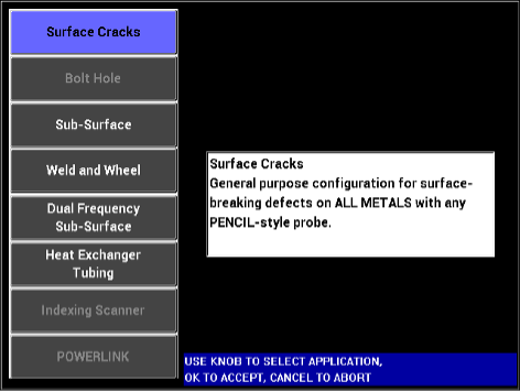
- Intuitive interface with “Application Selection” menu offering preset parameters
- All-settings configuration page
- 10 Hz to 12 MHz frequency capacity
- Automatic internal balance circuit (for BNC connector)
- Up to two real-time readings
- True automatic mixing
- Storage capacity of up to 500 files (program and data)
- Onboard file preview
- Multiple alarm configurations
If you’re curious about the eddy current flaw detector that astronauts used, download the brochure or contact Olympus to arrange a demo.
Related Content
Taking Flight with an NDT Level III—Aircraft Inspection Using Eddy Current Testing
Introduction to Eddy Current Testing
Get In Touch