Large reciprocating internal combustion engines (RICEs) are widely employed in many industries to generate electricity or drive mechanical equipment—propeller shafts and pumps, for instance. The working principle of these engines is the same as traditional automotive combustion engines, but on a much larger scale. Here, we discuss RICE condition monitoring techniques and the uses of borescopes, along with best practice guidelines and troubleshooting tips to get the most out of these types of inspections.
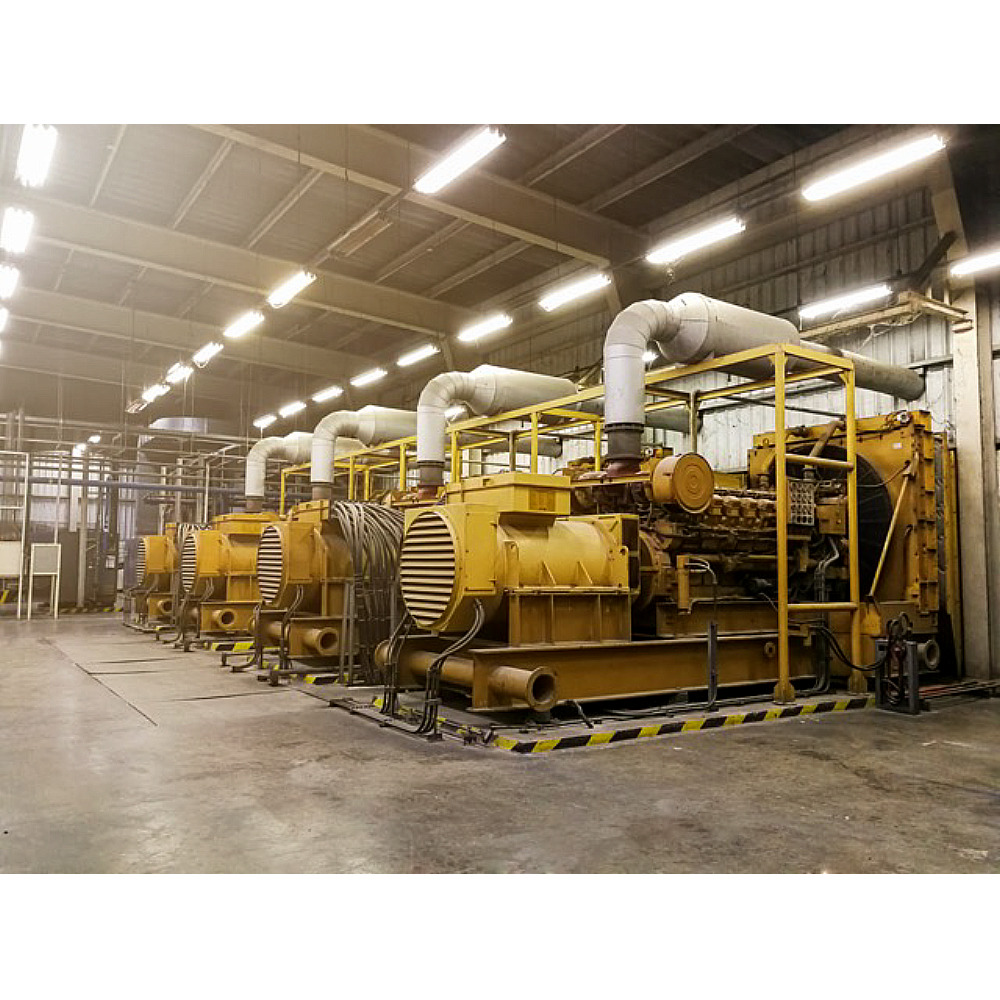
Figure 1 Reciprocating internal combustion engines
To run and maintain large engines efficiently, it is necessary to understand the condition of their components. This is accomplished using various condition monitoring (CM) techniques. Each technique provides one type of information about the engine. This list summarizes the most common condition monitoring techniques used for RICE inspections:
- Instrumentation – continuous monitoring of readings from engine sensors, such as temperature, pressure, vibration, exhaust gas composition, etc.
- Used oil analysis – periodical collection and laboratory analysis of oil samples, which may reveal degradation of the oil or the presence of particles that can be linked to contamination, wear, or damage.
- Borescope inspection (BSI) – visual inspection of internal parts of the engine with little or no need to disassemble parts.
- Strip down/dismantling – disassembling parts or the whole engine for inspection, overhaul, or to replace components.
Instrumentation and used oil analysis are noninvasive techniques, which require no interruption of RICE operation and are widely seen as the first approach to condition monitoring. However, because these techniques are limited in the information they can obtain, regular borescope inspection may be required, either as part of a preventative maintenance strategy or as a tool in reactive maintenance. The focus of a borescope inspection of a reciprocating engine is the combustion chamber, which is also called the cylinder. The components surrounding the combustion chamber are subject to high pressure and temperatures and therefore need to be monitored for damage and wear. In addition to the cylinder, other parts of the engine can also be inspected using a borescope, such as the water jacket, oil galleries and sump, turbochargers, cooling and air circulation systems, and alternators, among others.
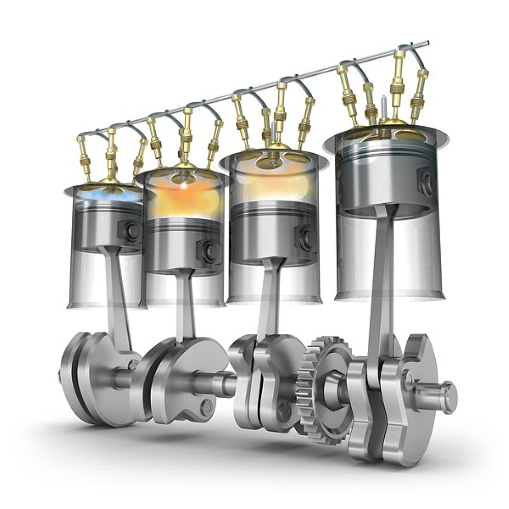
Figure 2 Representation of combustion chambers (cylinders)
Borescope Technology – A Long Legacy
Reciprocating engines have been around since the start of the 20th century and one of the initial applications of borescope technology was to inspect them. The first type of industrial endoscope to emerge was the rigid borescope, followed by the flexible fiberscopes. Today, videoscopes are state-of-the art in borescope inspection, due to their versatility, ease of use, and the ability to capture both images and video. Table 1 presents an overview of the characteristics of each of these systems. While there is still use for rigid borescopes and fiberscopes, this article focuses on videoscopes, due to their widespread application.
Table 1 Comparison of the main characteristics of rigid borescopes, fiberscopes, and videoscopes
| Feature | Rigid Borescope | Fiberscope | Videoscope |
| Insertion tube type | Rigid, straight-line access | Flexible, articulated | Flexible, articulated |
| Light source | External | External | Built in |
| Image acquisition | Optical, relay lenses | Optical, fiber bundle | Digital, imaging sensor |
| Optical system | Fixed | Fixed or changeable | Changeable |
| Screen, image, and video capture | Require additional accessories | Require additional accessories | Built in |
| Measurement | Not available | Not available | Possible |
As seen in Table 1, videoscopes have considerable technical advantages over rigid borescopes and fiberscopes. A borescope inspection performed using a videoscope will be faster (fewer parts to attach and fewer adjustments to make to achieve a good image), and it will also produce a better output for reporting, since images and videos can be easily recorded.
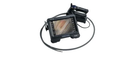
Within Evident’s remote visual inspection (RVI) portfolio, the videoscopes recommended for RICE inspection are the IPLEX™ G Lite and the IPLEX GT. Both videoscopes produce high-quality images, enabling component evaluation and further reporting.
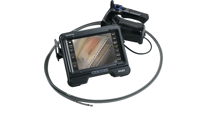 | 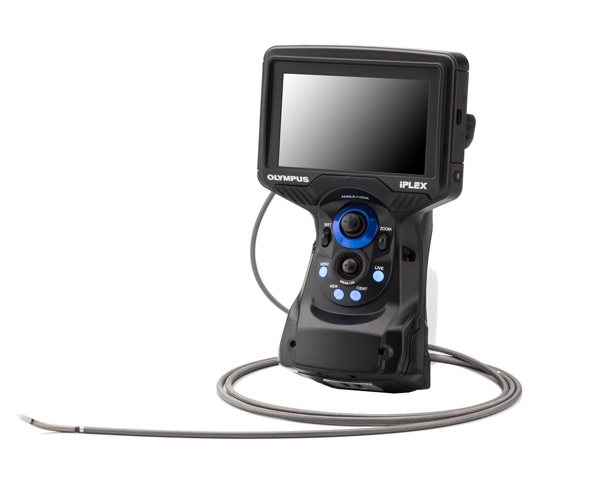 |
Getting the Right Configuration
- 6.6 ft length insertion tube
- 6 mm probe diameter
- Two optical tips:
- One side facing far focus tip (AT120S/FF) for an initial overview of the cylinder
- One forward facing near focus tip (AT120D/NF) for detailed inspection
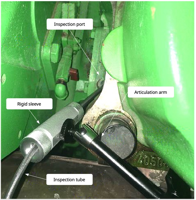
Figure 4 Rigid sleeve and articulating arm
Cylinder Inspection 101 – Best Practice
Preparing the Videoscope
- Before inserting the videoscope probe, check if you have the correct optical tip for the inspection, and ensure that the optical tip and distal end are clean.
Inserting the Probe into the Cylinder
- It is recommended to use the rigid sleeve when inserting the probe through the access port (as shown in Figure 3). This helps protect the probe, reducing the chance of oil contamination and probe damage. The rigid sleeve removes the need to hold the probe, improving image stability and reducing the chance of hitting the cylinder’s internal surfaces.
- Once the probe is inside, to obtain images with a repeatable orientation, rotate the probe until the direction of 12 o’clock is at the top of the image on the screen.
- Very often, it is possible to determine the directions of the cylinder by looking at the piston crown (top of the piston), which will have specific features or marks that are direction dependent.
Positioning the Piston
- Cylinder inspection must be done with the piston at the very bottom of the cylinder (bottom center). This enables the inspector to visualize the largest extent of the cylinder walls.
- To position a piston right at the bottom, observe the videoscope screen while cranking the engine manually until the piston is in the right position.
- To increase the efficiency of the inspection, you can sequence your inspection following the firing sequence, since several pistons have their positions synchronized.
- You can use the IPLEX Image Share app to visualize the piston position while cranking the engine.
Inspection
- Once the piston is positioned correctly, you can proceed with the inspection.
- We advise performing a general inspection using a side view (right angle) optical tip, with which you will be able to get an overview of the cylinder walls, piston, valve deck and valves, as shown in Figure 4.
- If additional detail is required, you can switch to a direct facing optical tip, which will enable detailed inspection closer to the target.
- For easier management of your recorded images, save the images of each cylinder in a separated folder in your memory device – this way, each image file will be named according to the folder name, and it will be easier to manage files and prepare your post-inspection report.
- Record images or video as required.
Removing the Probe
- Once you have finished inspecting a cylinder, unlock the probe articulation (watch for the padlock symbol on the videoscope screen, bending section is engaged)
- Remove the probe from cylinder.
- Move the rigid sleeve and articulated arm to the next piston to be inspected.
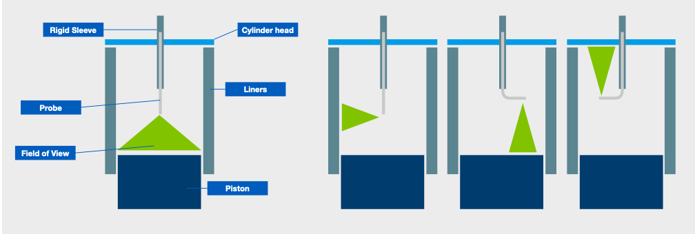
Figure 5 Scheme showing how to use a side facing optical tip to obtain an overview of the cylinder
Troubleshooting
| Challenge | Issues | Solutions |
| Oil | Most of the inspection will be done in the presence of lubricant, which may degrade image quality |
|
| Temperature | Depending how long before the inspection the engine is shutdown, the cylinders may still be hot when the inspection start |
|
| Probe orientation | Once the borescope is inserted in the cylinder, it may be difficult to determine the orientation of the images |
|
| Naming image files | If the user records images of different cylinders in the same folder, they will all have similar file names, and it is difficult to manage them after the inspection |
|