Application
Phased array inspection of aluminum aircraft skin for scribe marks and for cracks originating at fastener holes in lap-splice joints.
Background
The advantage of scanning laterally is being able to focus the beam in the lateral direction. Once the beam is focused in the lateral direction, the inspection clearly differentiates between the echoes coming from the geometry (such as fastener holes) and those coming from cracks. The use of the Sscan images facilitates the analysis for the operator.Users of ultrasonic phased array instruments are very familiar with the beam steering capability, where all the beams generated have different refracted angles and are all located in the same vertical plane. However, some tests use the steering capability in another way: they steer the beam in the lateral direction. In doing so, the skew angle of the beam changes while the refracting angle remains fixed. This probe and wedge configuration is very helpful for some applications such as the inspection of the lower skin of a lap-splice on aircraft. Typical defects that are detected are cracks protruding from fastener holes and scribe marks located on the aircraft fuselage. This technique shows great advantages when the crack is off-angle; in other words, when the crack orientations are not perpendicular to the beam direction. |
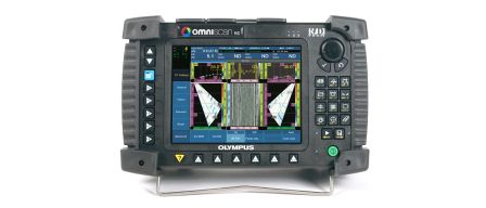
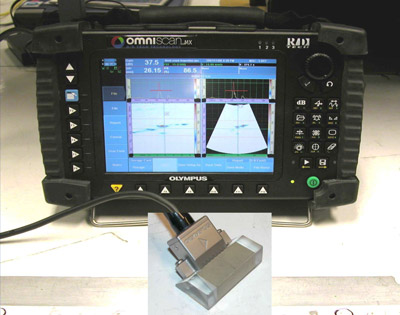
OmniScan with phased array probe mounted in the lateral configuration |
Equipment
• OmniScan MX or OmniScan MX2 16:128 or 32:128
• Multigroup function (highly recommended) ed to detect cracks along the lower fastener row. There are two configurations that can be used and they are presented as follows:
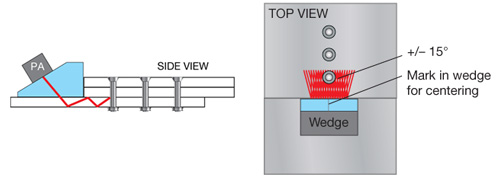
a. The first beam configuration consists of one lateral linear scan with a skew of 0 degrees, and one sectorial scan with skews of -15 degrees to 15 degrees. These scans are produced by one aperture of 16 elements, which is located in the center of the probe.
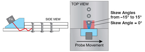
Lateral linear scan (red lines); lateral skewing scan (blue lines)
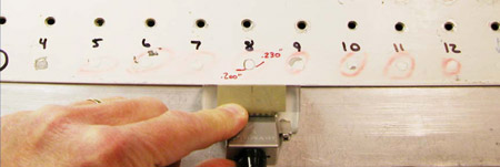
Picture of lap splice with cracks (1 mm thick skin)
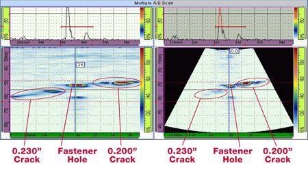
OmniScan print screen showing crack detection using first configuration.
Lateral linear scan (left); lateral skewing scan (right)
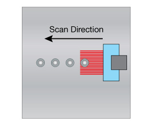
b. The second beam configuration is composed of three lateral linear scans set at different skew angles as shown in the figure below. In this example, the crack is strongly detected with the scan at 15 degrees. This example clearly shows the importance of the skewing angle when detecting cracks that have an oblique orientation.
The three lateral linear scans configuraton (red lines)
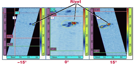
OmniScan print screen showing crack detection using the second configuration.
-15 degrees (left); 0 degrees (center); +15 degrees (right)
2. Aircraft Outer Wings Lower Surface Panel Inspection
The Lower Surface Panel Inspection is used to detect cracks located at the bottom and the top of the first skin on the outer wing of an aircraft. These cracks can be located either around or away from fasteners.
In this inspection, only one lateral linear scan with 0 degree skew is used with a 45 degree shear wave refracted angle.
Inspection of the outer wing, lower-surface panel
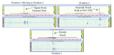
OmniScan print screen showing far-side and near-side notch detection using this configuration.
Conclusion
Lateral scan configurations demonstrate a high potential for sensitivity when finding cracks in fasteners. Cracks as small as 1 mm long can be detected with a very good signal-to-noise ratio. By using skewing angles, detection of oblique cracks is optimized. This probe and wedge configuration can be used for many other applications and should be evaluated during all inspection technique developments.