EPOCH XT
Discontinued Products
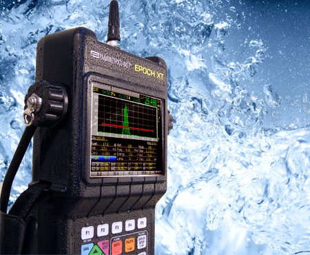
EPOCH XT: 最新の超音波探傷器
数多くの機能を標準装備した高性能な超音波探傷器です。調整可能な矩形波パルサー、選択可能な狭帯域および広帯域のデジタルフィルターなど。
概要
本製品は生産を終了致しました。 現行の製品を見るにはここをクリックしてください >>
Panametrics-NDT新型 EPOCH XT超音波探傷器は、あらゆる検査に柔軟に対応でき、かつ過酷な環境下での使用に対応できるよう設計されています。 EPOCH XTは、IP67規格に準拠した密封ケースの小型ユニットに多数の探傷と測定機能、高輝度マルチカラーLCD、多様なバッテリーオプション、強力なデータ管理機能、多数のソフトウェア機能を搭載しています。
主な特長
- EN 12668-1 に準拠
- IP67規格に適合 過酷な環境にも耐えうる気密設計
- 強力な DAC/TVG を標準搭載
- ダイナミックDAC
- 警告レベル線の任意選択
- ASMEとJIS 規格に準拠
- アドバンスTVGテーブルによりTVGのカスタマイズが可能
- 多様なバッテリーオプション - リチウムイオンバッテリー/NiMHバッテリー/乾電池
- ダイレクトプリントとUSBドライブへの保存を可能にするホストUSBポート
- PC送受信用のクライアントUSBポート
- "PerfectSquare™ テクノロジ": ピークおよび立ち上がりエッジの両方でパルスを電子制御することにより、探触子のパフォーマンスと近距離分解能を強化
- PRFは10 Hz から 1 kHzまで10 Hz ごとに増加.。 すべての測定が簡単な操作で可能
- パワフルな英数字のデータロガー
- 腐食厚さ計のファイル形式を内部設定
- 容易にファイルを追加
- マルチカラーLCDディスプレイ
- 軽量 2.1 kg
便利な計測機能を装備
EPOCH XTは、整調可能な矩形波パルサーや選択可能な狭帯域および広帯域デジタルフィルタ、0 から 110 dBまでのゲインレンジ、ピークメモリとピークホールド、調整可能なPRF、0.01 mmの 計測分解能およびプログラム可能なアラーム設定付きの2つのゲートなど、多彩な標準計測機能を備えています。 また、このユニットは標準仕様およびオプションでアプリケーションに特化したソフトウェア機能を提供します。:ダイナミックDAC/TVG (距離振幅補正/時間軸振幅補正)、オンボードDGS/AVG、AWS D1.1と D1.5、曲面補正、GageView Pro
- PerfectSquare™ テクノロジによる整調可能な標準矩形波パルサーにより、パルス幅を調整し、探触子のパフォーマンスを最大化することが可能
- 標準仕様デジタルレシーバフィルタリング-広帯域/いくつかの狭帯域設定/ハイパスフィルタ設定
- 検査要件に対応できるようカスタマイズ可能な5つの計測表示として、 各ディスプレイボックス毎にゲート1またはゲート2の計測を選択
- フルスクリーン高0.25% の振幅分解能
- フルスクリーン高0%から110%までの振幅表示
- ゲート計測モード: ピーク、エッジ、厚さ計アプリケーション用の新ファーストピークモード
- ライブスクリーン上で10 Hzから1000 Hzまで、10 Hz毎に増加する調整可能な測定レート
- すべての検波モードにおいてピークメモリとピークホールド機能 。RFモードでもピークホールドが可能
- 新グリッド表示モード
- 標準1~10
- ビーム路程距離
- 斜角検査用スキップ表示
- 選択可能な振幅表示 (100%または110%)
- 各ゲートごとにスキップ表示と計測モード表示
- 各ゲートごとにアラーム表示
新ダイレクトアクセスキーパッド
- 最適に構成されたカラーキーパッド
- 重要な機器設定パラメータへのダイレクトアクセス
- 英数字文字の直接入力
- カスタマイズ可能な5つのファンクションキーにより、設定値を迅速な操作が可能
- 英語、国際記号、日本語、中国語
複数のバッテリーオプション
EPOCH XTは、3つのバッテリーオプションを備え、ディスプレイ輝度とバッテリーの選択に応じて長時間の駆動が可能です。
- 内蔵充電式 : リチウムイオン、NiMH電池またはアルカリ乾電池
- 外部高性能バッテリー充電器
過酷な環境に対応
丈夫なEPOCH XTはIP67の規格に適合。 このユニットは、多湿環境から塵・砂の多い厳しい環境での現場作業に耐えることができます。
- BNCコネクタ仕様では、P67規格に沿った密封設計
- 広範囲な使用温度範囲:
- リチウムイオンバッテリー: -10° から 50°Cまで
- NiMHバッテリー: 0° から50°Cまで
- アルカリ電池: -10° から50°Cまで
- 充電時温度: 0°から40°Cまで
- ストラップは、左もしくは右手操作用に取付け変更可能
- 使いやすいゴム付きパイプスタンドは、折り曲げや取り外し可能
- 首にかけて使用できるDリングを装備した耐久性の強いユニット
- 密封バッテリー部:バッテリー交換には、ツールが一切不要
- ACアダプタとUSB接続用のI/O端子は密閉
- LEMOコネクタ採用:Oリング ゴムシール付き (ただし、この構成はIP67に適合していません)
豊富な文書作成機能とデータ管理能力
GageView Pro
オプショナルの GageView Proインターフェイスプログラムにより、保存した測定データを管理しフォーマット化を容易にします。 データの印刷もしくは、文書処理ファイルや詳しい集計表へのコピー・ペーストが、簡単に行えます。 GageView Proインターフェイスプログラムはまた、カスタマイズされた識別(ID)文字のデータベースを作成し、EPOCH XTにアップロードすることができます。 ライブスクリーンキャプチャモード、データベースバックアップ、保存、マルチビューウィンドウズなど新機能も搭載。 インターフェイスプログラムは、EPOCH 4、4B、4PLUS、LTおよびXTと完全に互換性があります。
- EPOCHに保存された厚さや波形データをExcelやWord等のプログラムにエクスポート可能
- 検査データベースを作成、フォーマット化と管理
- リアルタイムスクリーンスナップショットをインポート
- EPOCHとPCにおける設定をインポートおよびエクスポート
- カスタムDGSプローブライブラリを作成
- EPOCH操作ソフトウェアをアップグレード
2つのUSBポート
- コンピュータへの高速データ移送のためのUSBクライアントポート
- USBポート使用のプリンタに直接接続可能、またはUSBドライバなどへ重要な測定データのバックアップのための USBホストポート
- USB接続とAC入力アダプタは、蝶ねじによる開閉可能なドアにより密閉
ハードウェア入力/出力ポートオプション
- オプショナル16ピンHW I/Oポート
- アラーム出力
- トリガー入力/出力
- 16ピンI/Oケーブル対応
- PN: EPXT-C-16HW-6 (6 feet)
- PN: EPXT-C-16HW-20 (20 feet)
データロガーと文書作成
EPOCH
XTの洗練されたデータロガーは、多くの探傷検査と厚さ測定に応用できる幅広い機能を提供しており、簡単に操作できるよう設計されています。
EPOCH 4シリーズとPanametrics-NDT腐食厚さ計の技術を採用したEPOCH XTは、検査や厚さ測定調査の要件に適しています。
ニーズに合ったファイルタイプ:
- EPOCH 4タイプファイル
- シーケンシャル
- 2D、2D EPRI
- 2D custom point
- 3D
- Boiler
EPOCH XTはまた、オンボード報告書自動作成機能も搭載しています。 カスタムリポートヘッダーを設定し、USBホストポートを使い直接印刷することができます。