Inspection & Measurement Systems

超声波产品

EPOCH XT


xt-hand

EPOCH XT: 全功能超声探伤仪

EPOCH XT是一款高级便携式超声探伤仪。具有很多标准测量功能,其中包括可调方波脉冲发生器、可选窄带和宽带数字式滤波器、0~110 dB的增益范围、峰值记忆和峰值保持、可调PRF。

EPOCH™ 
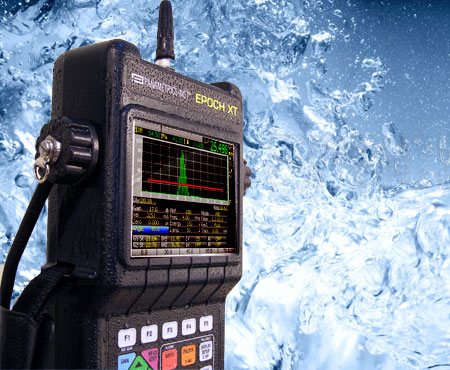
XT超声探伤仪的设计目的是要提高检测的灵活性以及加强仪器在恶劣环境下的适用性。该款探伤仪集多种强化的探伤能力和测量功能于一体,配有明亮的彩色液晶显示屏,可灵活选择电池类型,具有强大的数据管理功能,并配有多种软件功能。其机体小巧而坚固,其密封性外壳的设计符合IP67防护等级的要求。

特色

  • 符合EN 12668-1标准。
  • 通过了在爆炸性气体中使用,以及防振、防撞击的测试。
  • 密封外壳,符合IP67要求,可在严酷的环境下工作。
  • 动态DAC/TVG标准:
    • 动态DAC曲线;
    • 可定制报警级别;
    • 满足ASME和JIS要求;
    • TVG表可允许进行完全自定义的TVG设置。
  • 多种电池选择:锂离子电池、镍氢电池或C型电池。
  • USB主机接口,用于直接打印及将数据保存到USB驱动器。
  • USB用户接口,用于与计算机通讯。
  • "Perfect Square™ 技术":电子控制脉冲的上升沿和下降沿,可最大限度地优化探头性能和提高近表面分辨率。
  • PRF可调,范围为10 Hz~1 kHz,增量为10 Hz。所有测量值可通过"单扫"获得。
  • 功能强大的字母数字数据记录器:可在机设置腐蚀测厚仪的文件类型。
  • 简单的增量文件。
  • 彩色液晶显示屏。
  • 重量轻:2.1公斤。

汇集了实用测量功能

EPOCH XT汇集了许多标准的测量功能,其中包括一个可调方波脉冲发生器、可选窄带和宽带数字滤波器、增益范围为0 dB~110 dB、峰值记忆和峰值保持、可调PRF、0.01毫米(0.001英寸)的测量分辨率,以及两个带可编程报警的闸门。此外,仪器还配有许多标准的和作为选项的特殊应用软件功能:动态DAC/TVG曲线(距离波幅校正/时变增益)、在机DGS/AVG曲线、AWS D1.1和D1.5、手动或编码B扫描、曲面校正,以及GageView Pro接口程序。

  • 操作人员通过使用PerfectSquare™技术的标准可调方波脉冲发生器,可以调节脉冲宽度,最大程度的发挥探头的性能。
  • 标准数字接收器滤波:宽带、多种窄带设置及高通设置。
  • 5个测量显示,可完全由用户定制,以满足检测需求。为每个显示框任意选择闸门1或闸门2。
  • 波幅测量分辨率为满屏高的0.25%。
  • 波幅测量范围为满屏高度的0%~110%。
  • 闸门测量模式:厚度测量应用的峰值、边沿和首峰模式。
  • 测量率可调:在实时屏幕上,10 Hz~1 kHz,增量为10 Hz。
  • 所有整流模式下的峰值记忆和峰值保持功能。峰值保持功能还在射频模式下使用。
  • 新栅格显示模式:
    • 标准1~10格
    • 声程
    • 用于角度声束检测的跨度模式
    • 可选100%或110%垂直显示
  • 每个闸门的跨度指示器和测量模式指示器。
  • 每个闸门的报警指示器。

直接访问小键盘

  • 合理的以色彩区分功能的按键布局。
  • 直接访问仪器的主要设置参数。
  • 直接输入字母数字符号。
  • 5个自定义功能键,可快速选择预设值。
  • 配有英语、日语、中文或国际符号。

多种电池选项

EPOCH XT提供三种可长时间供电的电池选择。

  • 内置可充电电池:镍氢、锂离子、碱性C型电池
  • 可选外部"智能"型电池充电器

在恶劣环境中工作的能力

坚固的EPOCH™ XT的设计符合IP 67的要求。该仪器可在海上或沙漠中的各种严酷的现场环境中工作。

  • 设计符合IP67标准的环境密封要求。
  • 可在美军标准MIL-STD-810F程序1和国家防火协会规范NFPA 70E 500节1级2分段D组规定的爆炸气体环境中应用。
  • 通过了IEC 60068-2-27, 60 g,6 µs H.S.的防撞击测试,3轴,共18轴。
  • 通过了IEC 60068-2-6的振动(正弦振动)测试,0.03英寸DA或2克为50 Hz~150 Hz,20个扫查周期。
  • 工作温度范围宽泛:
    • 锂离子电池:-20°C~50°C
    • 镍氢电池:0°C~50°C
    • 碱性电池:-10°C~50°C
    • 充电温度:0°C~40°C
  • 电池存储温度:0°C~50°C
  • 手带可按左手或右手操作习惯安装固定。
  • 简单易用的可折叠或拆卸的涂胶管状支架。
  • 安装在仪器上的D型环坚固耐用,便于将仪器吊挂在胸前使用。
  • 密封的电池盒,不需工具即可更换电池。
  • 密封的输入/输出口,用于连接交流电源适配器以及连接USB。

强大的文档和数据管理能力

GageView Pro

可选GageView™ Pro接口程序帮助管理和格式化所存储的检测数据。数据可被打印输出或被方便地拷贝粘贴到文档处理文件和电子表格中,以备进一步编辑报告之用。GageView Pro接口程序还可以生成用户定制的ID标识字符串的数据库,以便上传到EPOCH XT仪器。新功能包括可在PC机上实时显示EPOCH XT屏幕视图的远程显示功能、实时屏幕捕捉模式、数据库备份/恢复、多视图窗口。接口程序与EPOCH 4、4B、4PLUS、LT和XT完全兼容。

  • 可将在EPOCH仪器中存储的厚度或波幅读数导出到Microsoft® Excel®、Word或相似的程序中。
  • 可生成、格式化和管理检测数据库。
  • 使用远程显示功能可在PC机上实时察看仪器视图。
  • 导入实时屏幕捕获。
  • 在Epoch和PC机之间导入和导出设置。
  • 可生成用户定制的DGS探头库。
  • 可升级EPOCH操作软件。

硬件输入/输出端口选项

  • 可选的16针硬件输入/输出端口
    • 报警输出
    • 触发器输入/输出
    • 编码器接口
  • 可提供16针输入/输出缆线
    • PN:EPXT-C-16HW-6(6英尺)
    • PN:EPXT-C-16HW-20(20英尺)

数据记录器和文档

EPOCH XT的精密数据记录器的设计宗旨是在为诸多缺陷检测和厚度测量应用提供大量功能的同时,简化操作过程。EPOCH XT仪器将EPOCH 4系列和Panametrics®腐蚀测厚仪的技术综合为一体,可充分满足用户的缺陷检测及厚度测量的应用需求。
为满足用户需要,备有以下文件类型:

  • 增量型
  • 顺序型
  • 2-D和2-D EPRI型
  • 2-D用户定制点型
  • 3-D型
  • 锅炉型

The EPOCH XT also offers onboard report generation. Operators may set up custom report headers and print directly from the instrument using the USB Host Port.

EPOCH XT的技术规格

一般规格
符合EN12668-1标准
重量:2.1公斤,包括锂离子电池
外型尺寸(高 x 宽 x 厚):277毫米 x 150毫米 x 51毫米(小键盘部分),71毫米(显示屏部分)
小键盘:英文、国际符号、日语或中文
语言:英语、西班牙语、法语、德语、意大利语、日语、中文、俄语、朝鲜语、挪威语、瑞典语
探头接口:BNC接口或者No. 1 LEMO®接口
电池:锂离子、镍氢电池、碱性C型电池
电池工作时间:锂离子:9~10小时,镍氢:5小时;C型电池:1~2小时
电源要求:AC主电源:100 VAC~120 VAC、200 VAC~240 VAC,50 Hz~60 Hz
环境等级
IP67:设计符合环境侵入保护评级的要求。
爆炸性气体测试:可在美军标准MIL-STD-810F程序1和美国国家防火协会规范NFPA 70E 500节的1级2分段D组规定的爆炸气体环境中应用。
防撞击测试:通过了IEC 60068-2-27,60 g,6 µs H.S.,3轴,共18轴。
防振动测试:通过了IEC 60068-2-6的振动(正弦振动)测试,0.03英寸DA或2克为50 Hz~150 Hz,20个扫查周期。
显示屏
彩色液晶显示屏:60 Hz刷新率,用户可选颜色和亮度,分屏和全屏显示模式。
显示屏尺寸(宽 x 高):320像素 x 240像素,彩色101毫米(4英寸) x 75毫米(3英寸)
基线中断模式:在全波模式下,射频波形上的零穿出点都显示为零点。
波幅栅格模式:100%或者110%波幅显示
时基栅格模式:标准0~10格,声程模式将声程范围分成5个相等的分区;跨度模式将声程跨距显示为栅格线。
脉冲发生器
可调方波脉冲发生器
PRF:在10 Hz~1 kHz范围内,用户可选或自动设定。
能量设置:50 V~475 V,增量为25 V。
脉冲宽度:25 ns~5000 ns可调。(0.1 MHz),使用PerfectSquare™技术。
阻尼:50 Ω、63 Ω、150 Ω、400 Ω
接收器
增益:0~110 dB,两个用户定义的增益步距的调整和预置在功能键之上。
仪器总带宽:0.2 MHz~26.5 MHz,-3 dB处。
数字滤波器设置:
0.2 MHz~10.0MHz
2.0 MHz~21.5MHz
0.2 MHz~1.2MHz
5.0 MHz~15.0MHz
0.5 MHz~4.0MHz
8.0 MHz~26.5MHz
1.5 MHz~8.5MHz
检波:全波、正半波、负半波、射频波
系统线性:水平:±0.2% FSW,垂直:0.25% FSH,放大器精度为±1 dB。
抑制:0%~80%满屏高,带有可视报警。
校准
声速和零位偏移的自动距离校准
检测模式:脉冲回波、双晶或穿透。
单位:毫米、英寸、微秒。
范围:1.86毫米~13400毫米。
声速:(635米/秒~15240米/秒)。
零位偏移:0 µs~4950 µs。
显示延迟:-59毫米~12700毫米。
折射角度:10°~85°,分辨率为0.1°。
测量
类型:闸门1和闸门2中的厚度、声程、投影、深度、波幅及传播时间。
回波到回波:标准。
5个测量显示位置:用户可从两个闸门的任何一个选择多达5个测量值,并将它们显示在实时屏幕上。
DAC/TVG标准:可捕捉的点多达50个, ASME、ASME III、JIS、80%~20%、自定义DAC及TVG表。110 dB动态范围,100 dB/µs调节,全增益、范围和设置过程中的延迟调整,视图可在DAC和TVG间切换。
自定义DAC,在+24 dB~-24 dB范围内最多有6条报警曲线。
TVG表格设置,用于高级时变增益应用。也可从DGS/AVG图形生成TVG设置。
波幅测量:0%~110%满屏高,分辨率为0.25%。
闸门
两个完全独立的闸门,用于测量回波高度和传播时间。
闸门起点:在全部显示范围内可变。
闸门宽度:在从闸门起点到显示范围的终点内可变。
闸门高度:在2%~95%满屏高范围内可变。
报警:正、负阈值;闸门1和闸门2的最小深度。
放大:显示范围为闸门1的宽度。
仪器输入/输出
USB用户端口:用于与GageView Pro通讯。
USB主机端口:可将数据直接传输到任何与PCL5兼容的激光或喷墨打印机上,还可将数据传输到USB驱动器的存储装置中。
LEMO®硬件输入/输出端口(可选):报警输出、触发器输入/输出、编码器接口
数据存储
可存储多达10000个带有波形、测量值及设置参数的标识码。

担保
一年有限保修。

标准配件
EPOCH XT仪器的基本附件包括:
EP-MCA:交流电适配器
EPXT-TC:储运箱
EPXT-MAN:仪器操作手册
EPXT-HS:双向手腕带
EPXT-PS:带橡胶保护层的不锈钢管支架
EPXT-BAT-L:锂离子电池
EPXT-BAT-N:镍氢电池
探头接口盖

选购配件
EPXT-EC:外接智能型电池充电器
EP4/CH:胸挂带
EPXT-RPC:橡胶保护壳(黑色)
EPXT-RPC-W:橡胶保护壳(白色)
EPXT-DP:透明屏幕保护膜(10个)
EPXT-C-16HW-6:16针硬件输入/输出电缆,附带连接示意图
EPXT-HWIO-B,L:硬件输入/输出选项
EPXT-EW:延长一年担保期限
EPXT-C-VGA-6:VGA缆线

软件选项
DGS/AVG:PN:EPXT-DGS-AVG
AWS D1.1 & D1.5:PN:EPXT-AWS
B扫描:PN:EPXT-BSCAN、EPXT-BSCAN-KIT-XX
浮动闸门:PN:EPXT-FG
高级滤波器:PN:EPXT-FILTERS
GAGEVIEW PRO软件:PN:GAGEVIEWPRO-KIT-USB

Software Options

Remote Activiation
EPOCH series advanced software options remotely activated at any time after acquiring the instrument. There is no need to send the instrument back for updates.

Availability On Instrument
The availability for each option on the various EPOCH 4 series instruments is defined using the following key:

Available/Optional Available/Optional Not available Not available Standard Standard

EPOCH Series
Software Modules XT
4+44BLT
API 5UEAvailable/OptionalAvailable/OptionalAvailable/Optional
AWSAvailable/OptionalAvailable/OptionalAvailable/Optional
ADTAvailable/OptionalAvailable/OptionalAvailable/Optional
Onboard DGS/AVGAvailable/OptionalAvailable/OptionalAvailable/Optional
Spotweld AssistantAvailable/OptionalNot availableNot available
Interface GateAvailable/OptionalNot availableNot available
High Pulse Repetition FrequencyAvailable/OptionalNot availableNot available
Low Pulse Repetition FrequencyAvailable/OptionalAvailable/OptionalAvailable/Optional
Floating GateAvailable/OptionalAvailable/OptionalNot availableNot available
Curved Surface CorrectionAvailable/OptionalNot availableAvailable/Optional
Spotweld OverlayAvailable/OptionalNot availableNot available
AutofreezeAvailable/OptionalNot availableNot available
Backwall AttenuatorAvailable/OptionalNot availableNot available
Wave AnalysisAvailable/OptionalNot availableNot available
Echo to EchoAvailable/OptionalStandardStandard
Narrowband FiltersAvailable/OptionalStandardNot available
Square Wave PulserAvailable/OptionalAvailable/OptionalStandard
Extended RangeAvailable/OptionalStandardStandard
Expanded MemoryAvailable/OptionalStandardStandard

API 5UE

Available/Optional Available/Optional Available/Optional Available/Optional Available/Optional
EPOCH XT EPOCH 4+ EPOCH 4 EPOCH 4B EPOCH LT

API 5UE - The API 5UE software option for the EPOCH 4 seriesis intended to assist with performing inspections in accordance with the American Petroleum Institute's Recommended Practice 5UE. This practice was developed specifically for OCTG manufacturers to inspect and characterize inner-diameter (ID) cracking in newly fabricated pipe. The API 5UE code uses two crack sizing methods to characterize ID cracking: the Amplitude Comparison Technique (ACT) and the Amplitude-Distance Differential Technique (ADDT). The software aids in performing the ADDT method, which is based on the formula:

d i=Amax(T 2-T 1)k

API 5UE inspections are accomplished using the Peak Memory function on the EPOCH 4 flaw detectors to draw a peak envelope of the crack signal and quickly capture the Amax, T1 and T2 points using a single key press. Using this collected data from the peak envelope, the EPOCH flaw detector performs the necessary calculation using the formula above and displays the crack height in the upper right corner of the screen.

The ADDT inspection method can also be performed using the API 5UE software in a manual mode, allowing the operator to manually select the values for Amax, T1 and T2. All API 5UE data can be easily stored using the EPOCH 4 series datalogger, and the full inspection data can be downloaded to a PC using the EPOCH 4 series interface program, GageView Pro.

AWS

Available/Optional Available/Optional Available/Optional Available/Optional Available/Optional
EPOCH XT EPOCH 4+ EPOCH 4 EPOCH 4B EPOCH LT

AWS - The AWS D1.1/D1.5 software option for the EPOCH 4 series is intended to assist with performing inspections covered under the American Welding Society D1.1 and D1.5 Structural Welding Code for steel. This code provides inspectors with a method to classify discontinuities found in welds using ultrasonic inspection. This code uses the following formula to develop an indication rating for a reflector found during an inspection:

A - B - C = D

A = Discontinuity Indication Level (dB)
B = Reference Indication Level (dB)
C = Attenuation Factor: 2 * (soundpath in inches - 1 inch) (dB)
D = Indication Rating (dB)

An AWS D1.1 inspector must take the Indication Rating (D) that is calculated based on A, B, and C to an Ultrasonic Acceptance - Rejection Criteria table produced by the AWS in order to classify the severity of the discontinuity that has been located.


AWS Indication Ratings are displayed in the upper right corner of the A-Scan display, as seen above. Once a proper angle calibration has been performed, the operator selects a reference indication and stores this indication gain level is as the "B" value using the AWS software option. All indications captured after this setup are assigned a "D" value automatically, eliminating the need for manual calculations. All data from AWS D1.1/D1.5 inspections can be saved and recalled at a later time using the EPOCH 4 series datalogger, including setup parameters, indication screenshots, and the values of A, B, C and D for each saved indication.

ADT

Standard Available/Optional Available/Optional Available/Optional Available/Optional
EPOCH XT EPOCH 4+ EPOCH 4 EPOCH 4B EPOCH LT

ADT - The Advanced DAC/TVG (ADT) software option is intended to significantly enhance the functionality of the standard DAC/TVG options already available on the EPOCH series flaw detectors, allowing users to customize inspections to their unique application requirements. The ADT feature incorporates the high-quality capabilities that adhere to ASME, ASME-3 and JIS sizing codes of standard DAC/TVG options with direct control of gain, range and zero offset, as well as reference and transfer correction. In addition, the ADT option provides new features such as 20%-80% DAC curves, customizable DAC curves, and a user-defined TVG table to meet advanced and unique inspection needs. ADT also allows the user to toggle between DAC and TVG views in many of its functions, allowing the operator the freedom to utilize both techniques during a single inspection.

Advanced DAC Options ADT's enhanced Distance Amplitude Correction functionalities allow more user control over the information acquired and displayed while sizing flaws compared to known reflector amplitude returns. A DAC curve is used to plot amplitude variations of signals from reflectors of the same size, but at different distances from the surface. A single DAC curve is used to plot the peak amplitude of each reflector at different depths within a material to compare with peak amplitude returns from unknown flaws. In the ASME-3 criteria, three DAC curves are plotted: one at peak amplitude, one 6dB below this point (indicating a reflector 50% the size of the reference), and one 14dB below the peak amplitude point (indicating a reflector that is 20% the size of the reference). Advanced DAC takes this functionality many steps further. The operator now has the option to customize up to three DAC curves at user-defined levels between +6dB and -24dB from the primary DAC curve. Additionally, since DAC curve inspections are not valid in most applications when a reflector is below 20% of full screen height, the ADT software allows a new dynamic 20%-80% function, which automatically adjusts the gain of reference signals below 20% up to 80% during setup. This allows a great range for inspections while minimizing the necessary manual gain adjustment. Should gain adjustment be necessary, the Advanced DAC and TVG functions now have a reference correction feature that provides the operator with a digital amplitude measurement of reflectors that is directly compared to the DAC curve level, even with significant gain adjustment during the measurement.

Custom DAC Curves (+6dB, -10dB, -18dB)
20%-80% DAC Feature
ASME-3 DAC Curve
ASME-3 DAC Curve in TVG View

Additionally, any DAC curve or curves set up using the standard or advanced functions are now interchangeable with TVG tables with a single push of a button.


Advanced TVG Options In addition to providing all the options from Advanced DAC in a TVG display for seamless integration of the two sizing techniques, the ADT software now offers a customizable TVG Table option for direct access to TVG point adjustment. This new feature allows fine manual adjustment of any captured TVG points, both for gain and position, as well as manual entry of new TVG points. The TVG Table is also completely compatible with the 1kHz High PRF option on the EPOCH 4 and EPOCH 4 PLUS instruments, as well as the Interface Gate option on those instruments, allowing for specialized fast scanning and on-line inspections previously out of reach of the EPOCH 4 series instruments.

TVG Table with Individual Point Adjustment
Resulting TVG Inspection Reference Definition

Onboard DGS/AVG

Available/Optional Available/Optional Available/Optional Available/Optional Available/Optional
EPOCH XT EPOCH 4+ EPOCH 4 EPOCH 4B EPOCH LT

Onboard DGS/AVG - The Onboard DGS/AVG option is a replacement for the old DGS/AVG option that has been available in the EPOCH 4 and 4 PLUS, which required a PC Interface Program for DGS/AVG setups. This new option allows complete DGS/AVG setups to be performed on the instrument.
The DGS/AVG method allows the operator to size defects based upon a calculated DGS/AVG curve for a given transducer, material, and reflector size, and has been designed to meet the requirements of EN 583-2:2001. This method requires that the operator only has one reference reflector in order to create a DGS curve for flaw sizing. This is much different than the DAC or TVG method which requires that the operator have representative defects at various depths within a part in order to create a curve for flaw sizing.
To allow the operator to setup DGS/AVG curves on the instrument very quickly, Olympus has developed a transducer library that is stored in the instrument's memory. All of the required data for building DGS/AVG curves is stored in the instrument's memory for each transducer in the library. The onboard DGS/AVG option provides the operator with rapid setup times and easy flaw size evaluation.

After activating the DGS/AVG software option and selecting the appropriate transducer from the probe library, the operator is walked through a series of instrument setups to display the DGS/AVG curve that correctly corresponds to the operator's particular inspection. These steps include defining a reference reflector, entering adjustment parameters for the critical flaw size of the inspection and entering parameters to compensate for material attenuation of the test piece and calibration block.
Upon proper completion of the instrument setup, the operator simply captures the reference reflector, and the DGS/AVG option displays the correct DGS/AVG curve on screen, along with any warning curves defined in the DGS/AVG setup parameters. When capturing potential defects, the DGS/AVG software displays the defect size evaluation in the upper right corner of the A-Scan display, allowing immediate and easy assessment of flaws. The software also permits adjustment of gain levels, which automatically adjust the displayed DGS/AVG curves, for more accurate inspection of potential defects.

DGS/AVG Curve and Warning Curve Capturing a Defect
Gain Adjustment in DGS/AVG Mode

Spotweld Assistant

Not available Available/Optional Not available Not available Not available
EPOCH XT EPOCH 4+ EPOCH 4 EPOCH 4B EPOCH LT

Spotweld Assistant (SWA) - The Spotweld Assistant software option is only available with the EPOCH 4 PLUS flaw detector, and is intended to provide automated weld quality analysis using a combination of the industry-proven Spotweld Overlay functionality with an advanced quality analysis algorithm. This software feature greatly enhances the EPOCH series' capability to inspect and characterize spotwelds with improved efficiency and accuracy.

Ultrasonic inspection of spotwelds involves the analysis of what is known as the "ring-down" of sound energy within the weld nugget. Unlike many direct-measurement techniques, spotweld inspection looks at the characteristics of the multiple echoes returned from sound ringing within the weld nugget to determine the quality of the weld. Echo spacing, sound attenuation, and intermediate echo detection are some of the indicators of weld quality analyzed by trained inspectors. Ultrasonic spotweld inspection is completely based on comparison between known "Good" and "Unweld" conditions with unknown welds, and requires a highly trained operator to perform a comprehensive inspection.

"Unweld" Reference Condition

"Good" Weld Reference Condition

The Spotweld Assistant is not intended to remove the necessity of a trained operator; instead, it is meant to enhance the ability of a trained operator to judge welds more efficiently. The operator begins by storing both a "Good" and "Unweld" reference condition into the EPOCH 4 PLUS to calibrate these control situations. The software then uses default comparative algorithms to rate unknown welds based on these stored conditions. If the trained operator disagrees with the software's recommended weld rating, the operator can override this rating manually.

SWA Automated Weld Rating


For more advanced users, the operator is able to manually adjust the comparative algorithmic parameters, such as Attenuation Analysis, Intermediate Echo Detection and Echo Spacing characteristics to allow a more customized and a higher quality automated weld-quality rating system.

The Spotweld Assistant option also has advanced features associated with the GageView Pro interface program. Using GageView Pro, the user can set up a full spotweld inspection plan. The operator can pre-define ID values for all welds to be inspected, all required SWA calibrations, and Memos reminding the operator to change transducers when calibrations change. The EPOCH 4 PLUS is capable of storing all weld rating information, including calibrations, waveforms, weld rating suggestions, and any operator weld rating overrides for recall and reporting purposes.


GageView Pro Inspection Plan


Exported SWA Excel File

Interface Gate

Not available Available/Optional Available/Optional Not available Not available
EPOCH XT EPOCH 4+ EPOCH 4 EPOCH 4B EPOCH LT

Interface Gate - The Interface Gate option is designed to graphically compensate for the change in a water path distance or other delay between the test material and transducer. When the option is activated, a third gate (Interface Gate) is visible on the EPOCH's display. You can position this Interface Gate in the area where you expect to detect the interface echo. The interface echo is a result of the sound energy reflection at the interface between the water path and the front surface of the test material. The Interface Gate maintains the interface echo on the left hand side of the EPOCH screen, regardless of the water path distance, thereby maintaining a precise "acoustic" zero from which the instrument makes digital measurements. The instrument's flaw gates (Gate 1 and 2) automatically track the location of the Interface Gate. The Interface Gate can be used in standard measurement mode or in Echo-to-Echo mode.


The Interface Gate is mainly used in immersion applications where the water path distance between the front surface of the test material and transducer face is continuously changing. The application may involve an "on-line" type approach with the test material moving steadily past a stationary transducer, or vice versa. If the front surface of the test material is not uniform, that causes slight differences in the water path distance.

High Pulse Repetition Frequency

Standard Available/Optional Available/Optional Not available Not available
EPOCH XT EPOCH 4+ EPOCH 4 EPOCH 4B EPOCH LT

High Pulse Repetition Frequency (PRF) - In many "on-line" immersion applications, the inspection pieces are passed by the transducer at a fast pace compared to normal, manual scanning. If proper care is not taken, this can result in an effect known as "interleaving". This occurs when a pulse is transmitted into the test material, but the transducer moves prior to the return signal, and it can result in the loss of important data. To compensate for this effect, the High PRF option is used to hold the rate at which a pulse is transmitted into the test material at a high value (1,000 Hz). This is commonly used in conjunction with the Interface Gate option for "on-line" immersion inspection of parts moving quickly by a fixed transducer.

Low Pulse Repetition Frequency

Standard Available/Optional Available/Optional Available/Optional Available/Optional
EPOCH XT EPOCH 4+ EPOCH 4 EPOCH 4B EPOCH LT

Low Pulse Repetition Frequency (PRF) - The Low Pulse Repetition Frequency option is available on all of the EPOCH series instruments, and is designed to hold the pulse repetition frequency (PRF) of the instrument to a fixed setting of 30 Hz. This option is commonly used in inspections that deal with materials that have very long sound paths, and is intended to avoid a phenomenon known as "wrap-around noise". When inspecting a piece with a long sound path at normal "Auto" PRF, there is a point when the time the sound takes to make a full round-trip from pulse to receive is longer than the time between pulses. If a test setup produces multiple echoes, then the issue is the length of time required for the last multiple echo to arrive at the receiver. Normally, the instrument builds a waveform response by pairing a certain pulse with its return signal and analyzing the characteristics of the return signal. However, in this situation, the received signal does not correspond to its initial pulse (according to the instrument's timing algorithm). The overall affect is the potential for random noise and echoes on the A-Scan display. The Low PRF software feature slows the pulsing of the unit and allows for a certain pulse to be correctly paired with its return signal.

Floating Gate

Not available Available/Optional Available/Optional Not available Not available
EPOCH XT EPOCH 4+ EPOCH 4 EPOCH 4B EPOCH LT

Floating Gate - The Floating Gate software allows the operator to track and make measurements from A-Scan echoes at either the -6dB or -12dB point. After activation and setup, the gate "floats" at either of these points and tracks changes in the amplitude of a captured signal. This feature is intended to take more consistent, precise readings, especially in Edge Detect mode, by always taking measurements from the same relative amplitude of an echo. The feature also helps to maintain constant measurements in scanning applications where quality of transducer coupling may vary. The Floating Gate software is included with the B-Scan software, and is commonly used in conjunction with Edge Detect mode and B-Scan to maintain the accurate acquisition of measurements from corroded pipe and other materials. Floating Gate can also be used with the Interface Gate to track amplitude changes in the interface echo.

Curved Surface Correction

Standard Available/Optional Available/Optional Not available Available/Optional
EPOCH XT EPOCH 4+ EPOCH 4 EPOCH 4B EPOCH LT

Curved Surface Correction - The Curved Surface Correction software is intended to adjust digital measurements from a curved inspection surface during angle beam inspection, to compensate for curvature effects on sound path length. The algorithms built into the EPOCH instruments to calculate sound path (V-path) distance, surface (skip) distance, and depth of a reflector when performing angle beam inspection are written for flat surfaces, such as welded plates. The measurement calculations are different in curved surfaces, such as pipes and cylinders, due to the more complex geometry of the part. Therefore, a separate algorithm has been written, the Curved Surface Correction, that requires the operator to input the outer diameter of the test piece and then calculates the correct V-path, skip distance and depth of a reflector. All other calibration settings, including verification of refracted angle and part thickness, must be entered correctly for accurate measurements.

Spotweld Overlay

Not available Available/Optional Available/Optional Not available Not available
EPOCH XT EPOCH 4+ EPOCH 4 EPOCH 4B EPOCH LT

Spotweld Overlay - The Spotweld Overlay software option provides stored templates for comparison of unknown spotweld conditions to known Good, Stick, Undersized, and other known weld conditions. Upon activation, the operator uses the five soft keys (F1-F5) on the EPOCH to store templates of known weld conditions. These templates can then be recalled to the screen over an unknown weld condition under interrogation (in live A-Scan or Freeze mode) for comparison purposes. Although this option was specifically designed for Spotweld inspection, its template and comparison capabilities can be used in a variety of applications.

Autofreeze

Not available Available/Optional Available/Optional Not available Not available
EPOCH XT EPOCH 4+ EPOCH 4 EPOCH 4B EPOCH LT

Autofreeze - The Autofreeze software option allows the operator to automatically freeze the live A-Scan when a gate alarm is triggered. This function is typically used in scanning applications or applications with signals that are difficult to obtain and/or maintain because of coupling or orientation issues. The operator activates a gate alarm and sets the gate parameters to capture only echoes of interest, and any echo that breaks the gate and triggers the alarm automatically activates the screen freeze function. This allows the operator to thoroughly inspection signals that may be difficult to catch or maintain in a live screen.

Backwall Attenuator

Not available Available/Optional Not available Not available Not available
EPOCH XT EPOCH 4+ EPOCH 4 EPOCH 4B EPOCH LT

Backwall Attenuator - The Backwall Echo Attenuator software option is only available in the EPOCH 4 PLUS, and is designed to independently adjust the gain in a screen range region defined by the Gate 2 start point and beyond. The Backwall Echo Attenuator option is commonly used with two specific forms of inspections, both dealing with very small defects. The first is an inspection where potential defects may not be oriented parallel to the direction of sound from the transducer. In this situation, sound will reflect from the defect but not return to the transducer due to the orientation of the reflector. Therefore, such defects are detected by monitoring for backwall signal loss or attenuation. This backwall amplitude change may be missed entirely if the backwall signal is saturated. The Backwall Echo Attenuator option allows the operator to monitor the backwall at a lower gain setting for any signal loss, while still scanning the remainder of the test piece at a high gain level for small defects. The second common inspection for the Backwall Attenuator is in porosity inspection. Because porosity tends to scatter sound instead of return a clear echo, backwall amplitude is sometimes the only way to positively differentiate porosity from material grain structure. The Backwall Echo Attenuator is again used to bring the entire backwall signal on screen to be closely monitored by the operator.

Wave Analysis

Not available Available/Optional Available/Optional Not available Not available
EPOCH XT EPOCH 4+ EPOCH 4 EPOCH 4B EPOCH LT

Wave Analysis - The Wave Analysis software option allows the operator to make precise point-to-point measurements from any two points along a waveform. This option activates to indexing arrows that trace the length of the visible waveform in the A-Scan view. Typically, the operator will capture a single echo waveform using the instrument gate and use the zoom function to view the waveform close up. The Wave Analysis software then allows the operator to trace the entire waveform with two arrows and take a measurement between these two arrows. A common application for the Wave Analysis software is the measurement of oxide scale on the opposite surface of a pipe or tube. The backwall echo is captured and zoomed using the instrument gate, and the Wave Analysis arrows are used to measure the distance between the peaks representing the inner and outer surfaces of the oxide layer, as seen below.

Echo to Echo

Available/Optional Available/Optional Available/Optional Standard Standard
EPOCH XT EPOCH 4+ EPOCH 4 EPOCH 4B EPOCH LT

Echo to Echo - The Echo-to-Echo software option allows the user to make a digital measurement between two echoes captured in Gate 1 and Gate 2 on the instrument. This common measurement technique is used to increase the precision of thickness readings by measuring between multiple echoes of a single thickness inspection, eliminating any couplant layer or surface condition discrepancies. This technique is also used to get a clear measurement from a near-surface echo that is obscured by the ringing of the main bang in its first reflection(s).

Narrowband Filters

Available/Optional Available/Optional Available/Optional Standard Not available
EPOCH XT EPOCH 4+ EPOCH 4 EPOCH 4B EPOCH LT

Narrowband Filters - Narrowband Filters allow the operator to variably tune out unwanted or unnecessary ultrasonic frequencies being received from the test piece into the EPOCH. This filtering can significantly better the signal-to-noise ratio of the A-Scan, particularly in non-homogenous or scattering materials. The Narrowband Filters have preset ranges to encompass commonly used transducer frequencies, but with the Advance User Filter setting from the EPOCH settings menu, the Filters can be tuned to custom low- and high-pass settings for optimization of the option's capability.

 Square Wave Pulser

Available/Optional Available/Optional Available/Optional Available/Optional Standard
EPOCH XT EPOCH 4+ EPOCH 4 EPOCH 4B EPOCH LT

Square Wave Pulser - The Square Wave Pulser is a powerful tool to improve penetration and response of transducers, particularly with low frequency probes and in highly attenuating materials. Unlike the standard, negative spike pulser of most UT inspection units, the tunable square wave pulser matches the EPOCH's excitation pulse duration to the frequency of a particular transducer, allowing the transducer to ring closer to its natural resonance and increase the amplitude of the signal transmitting into the test material from the transducer. This is especially useful with lower frequency transducers, as the natural resonant period of lower frequency transducers is longer than that of higher frequency tranducers and a traditional spike pulse does not obtain optimal results at these longer resonance frequencies.

2.25Mhz Probe with Square Wave Pulser
2.25MHz Probe with Spike Pulser - 12dB Difference!

Extended Range

Available/Optional Available/Optional Available/Optional Standard Standard
EPOCH XT EPOCH 4+ EPOCH 4 EPOCH 4B EPOCH LT

Extended Range - The Extended Range option increases the standard measurement range of the EPOCH LT and EPOCH 4B from 0.16 inches - 200 inches (4mm - 5,000mm) to the extended range of 0.038 inches - 400 inches (1mm - 10,000mm).

Expanded Memory

Available/Optional Available/Optional Standard Standard Standard
EPOCH XT EPOCH 4+ EPOCH 4 EPOCH 4B EPOCH LT

Expanded Memory - The Expanded Memory option increase the memory capacity of the EPOCH LT, EPOCH 4B and EPOCH 4 to allow the storage of more waveforms/calibrations and/or thickness readings. The memory is expanded according to the table below:

Expanded Memory Capacity Standart Memory Capacity
Thickness Readings 40,000 10,000
Waveforms 2,000 500

GageView™

The GageView and GageView Pro Interface Programs are Windows-based applications that collect, create, manage, and print data from Olympus thickness gages and flaw detectors.

GageView is compatible with gage models 35DL, 35DLHP, and MG2-DL. It provides the following capabilities:

  • Creating Datasets and Surveys
  • Editing stored data such as thickness data
  • Viewing Dataset and Survey file information including thickness readings, waveform, gage setup values, and transducer setup values
  • Downloading and uploading thickness surveys to and from the Panametrics ultrasonic thickness gages
  • Exporting Surveys to spreadsheets and other programs
  • Collecting snapshot screens (graphical data sent by a thickness gage that duplicates the exact screen display)
  • Printing reports such as Thickness, Setup Table, Statistics, Color Grid, and others
  • Upgrading gage operating software

GageView Pro is compatible with flaw detector models Epoch 4, Epoch 4B, Epoch LT, Epoch 4 PLUS, and Epoch XT, as well as the gage models listed above. When used with flaw detectors, GageView Pro provides the following capabilities:

  • Exporting thickness or amplitude data saved on the Epoch to Excel, Word, or similar programs
  • Create, format, and manage test databases
  • Export real-time screen snapshots, including B-scans, to a PC or printer
  • Import and export setups between the Epoch and a PC
  • Set up inspection plan templates, including pre-loaded probe calibrations, IDs, and memos
  • Create a custom DGS probe library
  • Upgrade Epoch operating software

EPOCH XT with inspector inspecting a pipe, with buggy

Our advanced digital ultrasonic flaw detector, the EPOCH XT, offers a fully encoded B-scan option that displays scanned thickness measurements of internally corroded pipe or tank walls as easy-to-read cross-sectional images. This time-saving B-scan option works with multiple crawlers and encoders providing important transducer location information of distance traveled. Complete with thickness markers the B-scan option provides readings at specific scan locations and the ability to automatically save A-scans for minimum thickness data or when triggered by alarm conditions.

Features

  • Bi-directional, uni-directional, and manual scan modes
  • Ability to simultaneously view A-scan and B-scan
  • Scanning resolution up to 0.020 in. (0.5 mm)
  • Fast scanning rate (variable based upon operator selectable resolution) of 20 in./sec. (500 mm/sec) with a resolution of 0.020 in. (0.5 mm)
  • Automatic audible alarm if scan speed exceeds limit
  • Operates in all test modes including Time Varied Gain (TVG) and Floating Gate
  • Floating Gate improves precision and consistency of thickness readings
  • Ability to save a single screenshot or an entire B-scan
  • Internal storage of up to 150,000 B-scan thickness readings per scan
  • Ability to scroll and review internally stored B-scan data
  • Audible and visual Minimum Depth Alarm for thickness below an operator defined level
  • Minimum Thickness continuously captured and updated on screen

Powerful Software and Reporting Capabilities

Color-coded Scan Views

The EPOCH XT BSCAN software features color-coded scan views for striking visual feedback. Triggering a Minimum-Depth Alarm changes the scan color from green to red, immediately alerting the operator of a critically thin area of material. By selecting the Color Gradient view, the B-scan image gradually shifts from red to green over the full thickness of the inspection window, allowing the operator to visualize thickness variations across the entire inspection range!

Color Gradient View
Alarm Color Change

Includes Floating Gate Software Option

Included with the B-scan software is the Floating Gate software option. This option allows the operator to "float" Gate 1 and/or Gate 2 at a selected height compared to a gated echo (-1 dB to -14 dB). This feature is intended to allow more consistent, precise readings, and is especially useful while acquiring B-scan data in Edge Detect mode.

B-scan with Floating Gate

B-Scan Options Specifications*

B-Scan Standard Kit

EPXT-BSCAN-KIT-XX Includes:
EPXT-BSCAN: B-scan operating software for the EPOCH XT
EP4/ENC: B-scan Position Encoder
EPXT-ENC-CBL-XX: Position Encoder Cable with specified cable length. (Cable lengths available 10, 25, 50, and 100 feet)
Notes:

  • Panametrics D790-SM, 5.0 MHz, 0.434 in. (11.0 mm) diameter, transducer sold separately
  • Panametrics BCMD-316-XXB or L1CMD-316-XXB transducer cables also sold separately
  • Transducer cables available in 5, 10, 25, 50, and 100 feet lengths
  • B-scan option can be added to existing EPOCH XT units remotely if the instrument is equipped with the Hardware I/O option.

Optional Accessories

EP4/ENC-PH: Probe holder assembly
EP4/MW: One pair of magnetic hold down wheels
EP4/EPB: Extension pole bracket
EP4/WC: Replaceable wear cap
EP4/EWC: Replaceable extended wear cap
GAGEVIEWPRO-KIT-USB: Interface Program on CD-ROM, includes USB interface cable

Encoder Specifications

Resolution: 50 pulses per inch (0.020 in. per reading) 2 pulses per mm (0.5 mm per reading)
Outputs: Standard quadrature position outputs, TTL/CMOS compatible
Power: Single +5 V supply provided by EPOCH XT
Connector: LEMO®, four conductor
Water Fitting: Bronze barbed fitting requires 5/32 in. (4.0 mm) ID tubing
Pipe Diameter: Minimum 3.0 in. (76.2 mm)
Dimensions: (L x W x H) 4.41 in. x 2.75 in. x 2.70 in. (111 mm x 69 mm x 68 mm)
Weight: 0.93 lb (425 g)
Construction: Rugged, sealed cast aluminum
Note: Other commercially available encoders or crawlers can be used with the EPOCH XT B-scan option.

Loading...

English | 日本語 | français | 简体中文 | Deutsch | italiano | čeština | magyar | Tiểng Việt | Español | русский | polski | português | 한국어