Solução para inspeção manual de soldaduras
Introduction
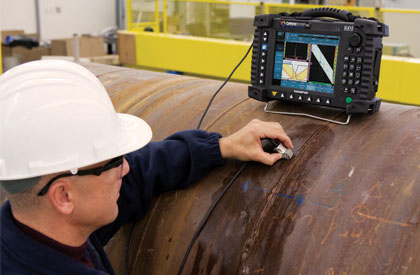
In many industries, such as in the oil and gas industry, countless welded tubes and pipes must be inspected throughout their entire service life. Olympus NDT has introduced an integrated weld inspection solution based on the field-proven OmniScan flaw detector and a new series of probes dedicated to manual weld inspection.
The manual weld-inspection solution from Olympus NDT, which includes the OmniScan M instrument and a new phased array (PA) weld probe series, provides major benefits: higher inspection speed, greater probability of detection, and better reporting and traceability. New features and improvements in the OmniScan M Weld software make this solution easy to use and well suited for PA and UT inspections. The solution is compliant with the most important standards: AWS, API, DGS, ASME-V, and JIS. In addition, a very helpful RayTracing™ feature allows the real-time visualization of the weld area covered by a PA configuration. An added benefit of PA is that only one phased array probe is needed to produce all inspection angles.
This manual inspection solution discussed here is based on:
- OmniScan M instrument
- OmniScan M Weld software adapted for manual weld inspection, featuring:
- UT flaw detector user interface and features
- Familiar menu-driven interface
- Sizing curves (DAC/TCG, ASME, JIS, and DGS)
- AWS and API code wizards
- Intuitive RayTracing™ feature provides a visual display of the phased array beams in the part
- Weld overlay feature simplifies data interpretation
- PA weld probe series
- Ergonomic design and smaller footprint
- DGS and AWS code-compliant PA probes
OmniScan® M Instrument
This low-cost, entry-level OmniScan M instrument brings the advantages of phased array imaging to manual testing, while keeping all the benefits of a proven product. The OmniScan M is a full-fledged member of the OmniScan UT product line dedicated to manual inspections, as illustrated in the product diagram below.
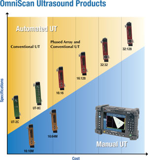
As is shown in the OmniScan Ultrasound Products diagram, Olympus offers a complete range of UT products enabling you to find exactly the price-point instrument your application calls for.
The OmniScan instruments are built to work in the harshest field conditions and offer a modular platform that allows you to switch among the different available test modules on location.
The OmniScan range of UT instruments includes two main categories: Automated UT instruments and Manual UT instruments. The yellow section of the diagram shows the Automated instruments comprised of Conventional UT and Phased Array instruments, all capable of encoded scans and data recoring.
The blue section of the diagram presents the Manual UT and Phased Array instruments.
As explained in this Application Guide, the OmniScan M is ideally suited for manual weld inspection.
Manual Phased Array Module (16:16M/16:64 M)
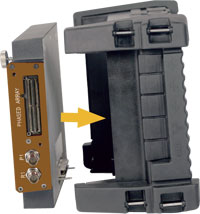
- Entry-level phased array module
- Flaw detector for manual UT inspections
- Real-time phased array imaging
- PA and UT combined into one instrument
- Simple flaw detector interface
Manual Weld Inspection Software
Flaw Detector User Interface
Because the OmniScan Weld software (MXU-M-2.1-WELD) is very similar to the standard software version (MXU-M-2.0), operators will be comfortable with what they already know. The OmniScan Weld software user interface provides access to parameters using three menu levels. The illustration below outlines the navigation syntax used to select menus, submenus, and parameter buttons, and to enter or select parameter values.
Menu > Submenu > Parameter = Value
Although the user interface remains very familiar, modifications have been made to ease navigation through the menus and to make the software more similar to other Olympus NDT flaw detectors (ex: the Epoch XT). With the new Weld software, operators already familiar with conventional flaw detectors will be able to easily use the OmniScan M in both UT and PA mode.
A good example of how the user interface has been improved is the UT Settings menu, which now includes all that is needed in inspection mode:
- Basic - (Gain, Start, Range, Wedge Delay, Velocity)
- Gates - (Start, Width, Threshold, Mode)
- Pulser - (Mode, Energy, Frequency, PRF)
- Receiver - (Filter, Rectifier, Reject, Averaging)
- Reference - (Set to 80%, Set Ref. dB)
The order in which the menu items, submenus, and parameter buttons appear corresponds to their typical sequence of usage.
In addition, the Preferences menu has been improved and now contains the various parameters related to the setup and system configuration that are typically used at the start of an inspection, such as the measurement unit (mm or in.) and the date and time.
Conventional UT Flaw Detector Features
Many of the features typically found in conventional UT flaw detectors have been provided in the new MXU-M-2.1 Weld software, giving operators all the same functionality as conventional UT flaw detectors available on the market (ex: the Epoch XT) through the conventional UT channel of the OmniScan M.
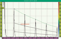
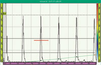
ADT - (Advanced DAC/TCG)
The new Advanced DAC/TCG (ADT) feature significantly enhances the standard DAC/TCG functionality available with the previous OmniScan M software version, allowing users to customize inspections to their unique application requirements.
The ADT feature incorporates high-quality capabilities that adhere to ASME, ASME-3, and JIS sizing codes, as well as customizable DAC curves to meet advanced and unique inspection needs.
ASME-3 DAC curves |
ASME-3 DAC curves in TCG view |
JIS DAC curves |
Custom TCG with individual point adjustment |

Each ADT type has its own "operating mode" allowing the operator to change the active curve and modify the DAC/TCG gain or the reference gain. In addition, new readings give useful information about the signal as regards the sizing curves.
A%Curve (or AdBCurve)
![]()
These readings display the difference, as a percentage (or in dB), between the amplitude peak value in the gate and the selected main DAC curve. This reading is also available for gate B (B%Curve or BdBCurve).
MaxA%Curve (or MaxAdBCurve)
![]()
These readings display the maximum difference, as a percentage (or in dB), between the amplitude peak value in the gate and the selected DAC curve. These values will be reset with the data reset and the selected DAC curve change. Therefore, as long as the instrument is in inspection mode, these two values will be affected by new maximum values. This reading is also available for gate B (MaxB%Curve or MaxBdBCurve).
Note: These readings can also be used with DGS curves.
Go to Wizard > Calibration > Type = Sizing and Mode = DAC (or TCG) for setup.
|
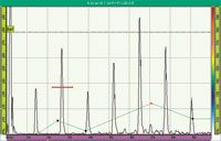
Onboard DGS/AVG
The DGS method allows the operator to size defects based upon a calculated DGS curve for a given transducer, material, and reflector size, and has been designed to meet the requirements of EN 583-2:2001. This method requires that the operator have only one reference reflector in order to create a DGS curve for flaw sizing. This is much different than the DAC or TCG methods, which require the operator to have representative defects at various depths within a part in order to create a curve for flaw sizing.
DGS curves
A step-by-step wizard helps the operator through a series of instrument setups to display the DGS curve that correctly corresponds to the operator's particular inspection. These steps include defining a reference reflector, entering adjustment parameters for the critical flaw size of the inspection, and entering parameters to compensate for material attenuation of the test piece and calibration block. At the end of the wizard, the DGS method also has its own adapted "operating mode" allowing quick modification of the Reg. Level, Warning Level, and Delta Vt values.
Equivalent reflector size
![]()
In addition, an ERS (equivalent reflector size) reading is now available. Based on the echo measurement in gate A and the DGS curves, this reading allows the operator to obtain the equivalent reflector diameter value in function of the calibration done during setup.
Go to Wizard > Calibration > Type = Sizing and Mode = DGS for setup.
|
AWS D1.1/D1.5
The AWS D1.1/D1.5 feature is provided to assist with performing inspections covered under the American Welding Society D1.1 and D1.5 Structural Welding Code for steel. This code provides inspectors with a method of using ultrasonic inspection to classify discontinuities found in welds. The Structural Welding Code uses the following formula to develop an indication rating for a reflector found during an inspection:
A - B - C = D
Where:
A = Discontinuity indication level (dB)
B = Reference indication level (dB)
C = Attenuation factor: 2 * (sound path in inches - 1 inch) (dB)
D = Indication rating (dB)
AWS rejection critera
![]()
An AWS inspector must take the indication rating (D) that is calculated based on A, B, and C to the "Ultrasonic Acceptance - Rejection Criteria" table produced by the AWS in order to classify the severity of the discontinuity that has been located. The AWS D reading allows this indication rating value to be obtained.
Once a proper angle calibration has been performed, the operator selects a reference indication and stores this indication gain level as the "B" value using the AWS feature. All indications captured after this setup are automatically assigned a "D" value, eliminating the need for manual calculations.
AWS class reading
![]()
In addition, the OmniScan has embedded AWS D1.1 and D1.5 tables and can automatically classify the severity of a discontinuity. The reading which shows this information is AWS CL.
Go to Wizard > Calibration > Type = Sizing and Mode = AWS for setup.
|
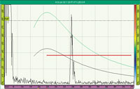
API 5UE
The API 5UE feature is included to assist with performing inspections in accordance with the American Petroleum Institute's Recommended Practice 5UE. This practice was developed specifically for OCTG manufacturers to inspect and characterize inner-diameter (ID) cracking in newly fabricated pipe. The API 5UE code uses two crack sizing methods to characterize ID cracking: the amplitude comparison technique (ACT) and the amplitude-distance differential technique (ADDT). The OmniScan API 5UE
feature aids in performing the ADDT method, which is based on thefollowing formula:
di = Amax (T2-T1) k.
The API 5UE setup wizard is used for a peak envelope of the crack signal to be drawn and for the Amax, T1, and T2 points to be captured quickly.
API-DL crack height
![]()
Using the data collected from the peak envelope, the OmniScan performs the necessary calculation using the formula for the ADDT method (given above) and displays the crack height using the API-DL reading.
API-HW half wave
![]()
An API-HW reading, giving the half-wave width that is 6 dB lower than the amplitude peak in gate A, is also available.
Go to Wizard > Calibration > Type = Sizing and Mode = API for setup.
|
Advantages of Phased Array Imaging
Using phased array imaging is an improved way of visualizing what are in fact the same signals as those obtained using conventional UT. Improved imaging becomes possible simply by color encoding the A-scan signals. The illustration below provides an example of a color-encoded view of a conventional UT beam.
By using the electronic scanning capability of phased array technology, imaging becomes possible without mechanical movement.Arrays are multiplexed using the same focal law and the resulting A-scan of each beam is color-encoded and displayed in a linear S‑scan (below, left). Because of the short distance between each element in a phased array probe, the electronic scan resolution is very precise (below, right).
Why not apply the advantages of phased array imaging to conventional flaw detector sizing methods? This is exactly what we have done for you!
ADT (Advanced DAC/TCG) Phased Array
By using an S-scan view for fast detection and an A-scan for conventional sizing methods (DAC/TCG, ASME, ASME-3, JIS, and custom), it is now possible to perform true flaw detector inspections that include the advantages of phased array technology. The OmniScan M can provide a different ADT curve for each beam of your phased array scan, providing the capability to inspect all angles with a single configuration. With phased arrays, there are different ways to build your ADT curves.
1) Single angle inspection
Very similar to conventional UT. Use only one angle of interest and use a small S-scan view to easily detect your defect position and quickly position the maximum amplitude point on your measurement angle. Then, only this angle has to be calibrated.
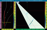
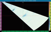
35° to 55° S-scan for a single 45° angle inspection with custom DAC in phased array
Go to Wizard > Focal Law > Start building a sectorial scan (ex: 35° to 55°).
|
2) Multiple angles inspection
A different ADT curve can be built manually on several angles of your S-scan. A new 3 A-scan and 1 S-scan layout is available, giving the operator the ability to quickly visualize up to 3 A-scans without having to change the angle data-cursor position. In this way, only angles of interest are used for sizing. For example, using 45°, 60°, and 70° angles in the same S-scan, you can perform sizing on these three angles using the same configuration (probe and setup)-exactly as is usually done
with a conventional UT A-scan inspection, but without the need for 3 different probes.
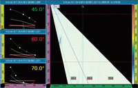
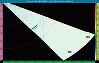
Independent DAC curve for multiple angles inspection in phased array (3A-S layout)
Go to Wizard > Focal Law > Start to build a sectorial scan (ex: 40° to 75°).
|
3) Full angles inspection
The OmniScan M has a powerful tool allowing each angle of the S-scan view to be quickly and easily calibrated. A useful wizard helps the operator to perform this full calibration step by step. In this way, all angles can be used to inspect and size the defect.
ADT wizard assistance for full angle calibration
Go to Wizard > Focal Law > Start to build a sectorial scan (ex: 35° to 55°).
|
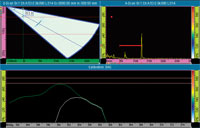
Onboard DGS/AVG Phased Array
Using a new DGS PA probe, DGS curves become available with phased array! A DGS wizard guides the operator through the steps required to calibrate the sensitivity and set up the DGS curves for each angle (45°, 60° and 70°). A very useful sensitivity interpolation is automatically calculated and applied to the other angles of the S-scan view for a smooth imaging display. In addition, the 3A-S layout is used in order to simultaneously display these three angles on the screen for DGS sizing.

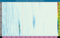
3A-S layout for DGS phased array inspection
Go to Wizard > Focal Law > Start to build a sectorial scan (ex: 40° to 75°).
|
AWS D1.1/D1.5 Phased Array
Exactly as with the DGS PA probe mentioned above, the new AWS PA probe brings the AWS sizing method to the world of phased array! An AWS wizard and an automatic sensitivity interpolation applied to the S-scan and the 3A-S layout are also available in order to quickly set up, calibrate, and use the 45°, 60°, and 70° angles in phased array mode.
Go to Wizard > Focal Law > Start to build a sectorial scan (ex: 40° to 75°).
|
Advantages of Phased Array Imaging: Summary
All the developments for the PA software explained in this Guide allow crack sizing to be performed the same way as with conventional UT-but phased array technology brings these added advantages:
- FASTER speed of inspection
- BETTER probability of detection
- REPORTING and traceability
- ONE phased array PROBE for all angles
Simplified Phased Array Interpretation
The intuitive RayTracing™ feature simplifies phased array interpretation for manual weld inspection and dramatically reduces the training time required for the operator. RayTracing is an embedded software tool that allows the weld area covered by your phased array configuration to be visualized in real time. RayTracing is therefore useful to help the operator to localize defects during analysis and can make phased array testing for manual weld inspection much simpler.
RayTracing in Setup Mode
In setup mode, RayTracing is presented by way of an interactive wizard displaying the part, the weld, and the zone covered by the focal law configuration.
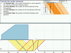
Wizard assistance for full angle calibration
Go to Wizard > Group > to start the first step of the wizard allowing you to create your weld shape.
|
RayTracing in Inspection Mode
In inspection mode, using the A-S-R layout, a RayTracing view helps the operator to localize the position of a defect in the weld. Also, a weld overlay on S-scans allows an indication in the S-scan to be linked with the weld position. In addition, a RayTracing operating mode allows access to the parameters of the RayTracing view and easy modification of these parameters during the inspection (ex: index offset, skew, weld zoom, leg quantity).
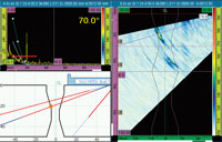
A-S-R layout in inspection mode
Go to Display > Selection > Layout = A-S-R to display the RayTracing layout.
|
RayTracing in Analysis Mode
In analysis mode, a table of indications can be used to record the information for each defect detected in the S-scan. For each table entry, a color point will be added on the RayTracing view. Then, this image can be used to create easy-to-understand reports.

RayTracing and indication table in analysis mode
Reporting using RayTracing
Press the Freeze shortcut button to go into the analysis mode.
|
Additional Features
Shortcut Improvements
Gain button, Start button, Range button, and Data Cursor button
| A new popup dialog box for the Gain, Start, Range and Data Cursor shortcuts allows values to be modified without having to change the menu being used. This popup dialog box appears in the top-left corner of the screen and allows the value to be changed by using the scroll knob or the alphanumeric keypad. |


Cursor button
| The Cursor shortcut allows toggling between each cursor of the selected view and allows each view to be quickly moved, one-by-one, using the new popup dialog box mentioned above. |

Gate button
| The Gate shortcut also toggles between the position parameters of each gate and displays the new popup dialog box mentioned above to modify the value. |

Zoom button
| The Zoom shortcut is now available. This new shortcut allows zooming in/out of the box zone created with the cursors of the selected view. |

Go to Measurement > Cursors > View to select the current view of the Cursor shortcut.
|
Overlay Setup
The Overlay submenu has been redesigned in order to allow a greater versatility for your display preferences:
- Independent on/off display indicators for law number, angle, legs, reference amplitude line, grid, weld overlay, and cursors.
- Independent gate display list for A only, A and B, A and I, or All display.
Go to Display > Overlay to set up your indicator display preferences. |
UT Display Mode
True Depth mode
In true Depth mode, the gates and the cursors are in cartesian mode and rulers are available only with a distance unit (mm or in). Two depth display types are available in this mode: one base on the UT range of all the focal law (All) and the second base on the UT range of the current focal law (Current Law).
"All" display type in True Depth mode |
"Current Law" display type in True Depth mode |

Sound Path mode
In Sound Path mode, the gates and the cursors are in polar mode and rulers are available in both time (us) and distance (mm or in) unit.
Sound Path mode
Uncorrected mode
In Uncorrected mode, there is not volumetric display correction apply on the S-scan view. Indeed, each focal law is display next to the other. The X ruler of the S-scan is the UT sound path and the Y ruler simply represents the number of each focal law. In this mode, rulers are available in both time (us) and distance (mm or in.) unit.
Uncorrected mode
Go to Display > Properties > Select = All to change the UT display mode |
MXU-M-2.1-WELD Software on an Automated Module
The manual weld inspection software (MXU-M-2.1-WELD) can also be used with an OmniScan MX that has a 16:128 or 32:128 module. The user has only to install both the MXU and the MXU-M software applications on the CompactFlash (CF) card and to select the appropriate menu at the OmniScan startup.
Phased Array Weld Probe Series
As a world leader in PA probe manufacturing, Olympus NDT has once again proved its superior applications knowledge with the introduction of the all new Weld Probe Series. Addressing multiple opportunities for improvement, this new series raises our best-selling A1 and A2 probes to a new level. Every aspect of the probes has been examined and optimized for more inspection possibilities and a more ergonomic design. The smaller housing and wedge footprint allow closer access to the feature being inspected for a better beam coverage. In addition, the improved ergonomics makes the probe more comfortable to hold during manual inspection. As explained in this application guide, the OmniScan M is ideally suited for manual weld inspection because of its affordable price and its simplicity of use. To perform a single-channel scan inspection, the best probes in the phased array Weld Probe Series to use with the M unit are the following:
- 5L16-A10
- 5L64-A12
- DGS Phased Array Probe (2L8-DGS and 4L8-DGS)
- AWS Phased Array Probe (2.25L16-AWS)
Of course, the advanced OmniScan MX modules can also be used for manual inspection, even though they offer more advanced features. In fact, the advanced modules have the significant advantages of allowing more elements for the probe aperture and a multiple-channel scan inspection. The following two probes maximize the OmniScan MX module capabilities:
- 5L32-A11
- 10L32-A10
How to Select Phased Array Probes
The following table explains the advantages of using each one of the probes for manual weld inspection (with any type of module from the OmniScan product line).
| Weld Probe Series | Typical applications and advantages | |
|---|---|---|
| 5L16-A10 | 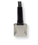 |
|
| 10L32-A10 | |
|
| 5L32-A11 | 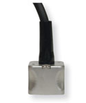 |
|
| 5L64-A12 | 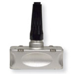 |
|
| 2L8-DGS | 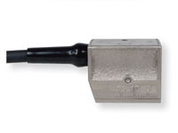 |
|
| 4L16-DGS | |
|
| 2.25L16-AWS | 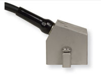 |
|