Measuring Microscope STM6
Discontinued Products
Descripción
This product has been discontinued, check out our current measuring microscopes >>
The STM6 microscopes offer excellent versatility and high performance three axis measurements of parts and electrical components, with sub-micron precision. Low magnification option makes this ideal for toolmakers.
- Space-saving Design/ High-accuracy Stages to Meet Customer Requirements
- High Measuring Accuracy and Durability
- The STM6 Was Designed with Emphasis on Ease of Use
- Automated Focusing System Provides Superior Repeatability
- Accessories that Widen the Range of Observation and Measurement
- System for Achieving More Advanced Measurement
Space-saving Design/ High-accuracy Stages to Meet Customer Requirements
Small Footprint
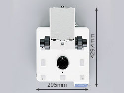 Space-saving Design | This model has a space-saving, compact design while retaining the various functions required in today's environment. (295mm in width and 429.4mm in depth). |
Four Different Optional Stages
 Coarse/Fine-feed Coaxial Wheel | One of four types of stages can be selected according to your requirements. Three of the stages (50x50, 100x50, and 100x100) employ a coarse/fine coaxial wheel while the 150x100 stage employs a clutch-free mechanism, achieving quick displacement and fine positioning. |
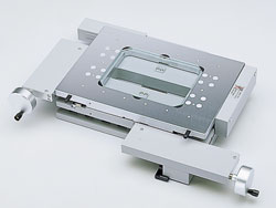 MM6C-CS150 (150x100 Table) | 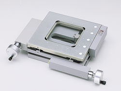 MM6C-CS100 (100x100 Table) |
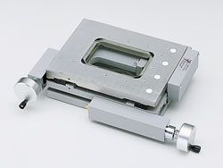 MM6C-CS100R (100x50 Table) | 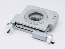 MM6C-CS50 (50x50 Table) |
High Measuring Accuracy and Durability
High-rigidity Body and Stage Resistant to Atmospheric Changes
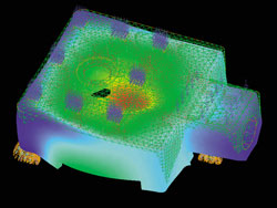 FEM Analysis | Maintaining accuracy is of paramount importance in any measuring instrument. In addition, retaining rigidity over long periods of time is crucial for reproducible measurements. Olympus has developed a high-rigidity body and precise stages that are resistant to atmospheric changes. The adoption of a linear guide mechanism and the incorporation of an original linear scale allows Olympus to meet the measurement needs of client with high reliability. |
Optical Linear Scale that Provides Sub-micron Resolution
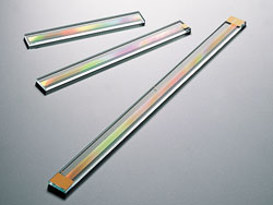 Optical Linear Scale | Scale accuracy is a key point to determine the accuracy of a measuring microscope. The STM6 electrically processes and measures the optical information obtained through Olympus' optical linear scale. |
Traceability System to International Standards
Olympus maintains the highest-level environment throughout the stages of production and assembly to ensure high precision. At our temperature-controlled plant, skilled Olympus engineers perform high-precision machining of carefully selected component materials, delicate finishing processes and final adjustments. All component parts and completed products are fully controlled under a rigorous traceability system.
Measuring Microscopes Traceability System
The STM6 was Designed with Emphasis on Ease of Use
Motorized Focus Unit Available for Quick Z-axis Measurement
The STM6 has adopted a motorized focus unit that significantly improves operability when focusing and measuring a height or depth. 5 step control over the speed of the vertical Z motor, greatly reduces fatigue during operation.
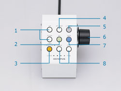 Z-axis Control Box |
|
Counter Located at the Ideal Observation Position
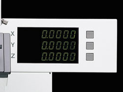 Counter | The integrated counter is mounted on the microscope body, with the display unit located a eye-level for simple observation. The operator can thereby confirm a measuring value with only a slight movement of the eye, allowing concentration on the specimen under observation. |
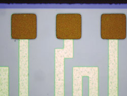
UIS2 Optical System and LED Illumination Enhances Edge Detection
The STM6 employs Olympus' UIS2 optical system that achieves superior resolution and contrast, and LED illumination that delivers faithful color reproduction independent of changes in brightness. This greatly improves the detection of edges, thus resulting in dramatic improvement in measurement repeatability. The LED illumination is also free from flickering and brightness fluctuation, reducing eye fatigue even over extended periods of operation.
 White LED | 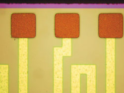 Halogen Lamp |
Reticles are Used for Easy Positioning
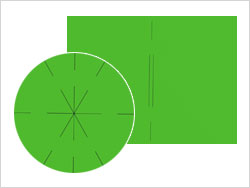 Reticle | Accurate alignment between the object being measured and the reticle is critical to any measuring microscope. In straight-line alignment, the use of a reticle and a dotted line will produce more accurate results than using a single line. Olympus has further improved alignment accuracy by using a reticle and a dotted line on the focusing plate. |
Automated Focusing System Provides Superior Repeatability
High-accuracy Auto Focus System (available as an option)
This laser-based focus system provides two modes of functions: one-shot and trace. Visual measurement of a height or a depth, which requires subtle operations, can be automated by selecting either mode. This significantly improves the efficiency and reproducibility of Z-axis measurements while allowing continued observation while using both hands on the stage control knobs.
[One-Shot Mode]
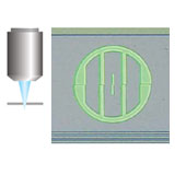
This mode provides instant focusing in the center of the field of view through the execution of the auto focus.
[Trace Mode]
This mode always maintains the state in focus while moving the stage across a sample. This greatly improves the operating time.
| List of Auto Focus Performance for Each Objective Lens | ||
| Objective Lens | Repeatability(2σn-1)*1 | Spot diameter *2 |
| LMPLFLN20x | 2µm | ø5µm |
| LMPLFLN50x | 1µm | ø2µm |
| LMPLFLN100x | 1µm | ø1µm |
*1 : Indicates a value based on Olympus reference specimen.
*2 : Indicates a theoretical value by calculation.
Focus Navigator Achieves High-accuracy Height Measurement and Increased Reproducibility
Olympus Focus Navigator system improves reproducibility during focusing by aligning the vertical displacement of the index pattern projected on the specimen. The focus navigator improves the repeatability in height measurement and reduces measurement variations due to personal difference, compared with visual focusing. The index pattern is compatible with various specimens simplifying focusing to contribute a dramatic reduction in measurement time. The Focus Navigator unit is compatible with reflected brightfield and reflected darkfield observations with objective lenses of 10x through 50x.
| Focus Navigator Alignment Image | ||
 Focus Point on the Front Side | 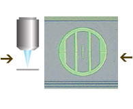 Focus Point Just in Place | 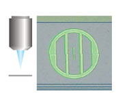 Focus Point on the Rear Side |
Accessories that Widen the Range of Observation and Measurement
Reflected Illumination Units
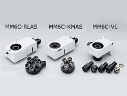 Reflected Illumination Units | Three types of reflected illumination units are available to support a variety of measuring ranges. These illumination units are capable of brightfield, darkfield, or differential interference contrast observation, corresponding to measuring objective lenses or metallurgical objective lenses with a revolving nosepiece. |
Rotary Table
This table can perform leveling of a specimen with ease.
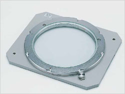 MM6C-RS2 rotatable stage, type 2 (For MM6C-CS150) | 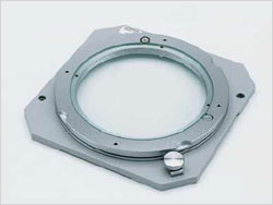 MM6C-RS1 rotatable stage, type 1 (For MM6C-CS100R and MM6C-CS100) |
White LED Illumination Unit
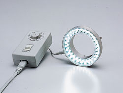 Rotary Table *The model of the LED illuminator may vary with area. | This white LED light source unit features a long service life, power savings, a reduction in size and weight, and high performance with no flickering or brightness fluctuation. |
4-divided LED Illumination Unit
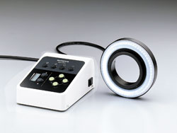 4-divided LED Illumination Unit | This reflected LED ring-light illuminator provides high color temperature and clear images. This unit provides 4-divided independent illumination and allows you to select an optimal illumination mode from among a total of 13 patterns. |
Recording and Storage of Digital Images is Possible with a Digital Camera.
A digital camera can be attached to the STM6's trinocular tube. This allows recording and storage of digital images, facilitating report generation. Choose from Olympus' wide range of digital cameras based on your application in terms of image quality, functions, and operability.
> Click here for Olympus' lineup of digital cameras
System for Achieving More Advanced Measurement
Arithmetic Device Equipped with Versatile Functions
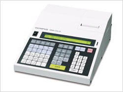 Geometric Calculator MM-CAL22 *MM6-CAL22 may not be available in some area. | The STM6 measuring microscope can start measurement immediately after placing a specimen on the stage Two-dimensional arithmetic processing can be performed simply by entering point data, displaying the descriptions of alignment item and measuring item during measurement on the display unit. Also, measurement results are outputted from the built-in printer. |