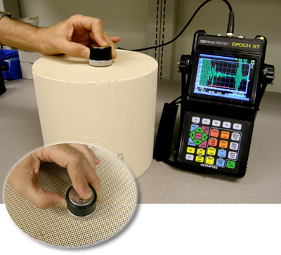
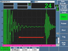
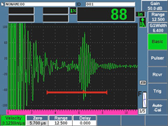
Application In the example below representing a setup with a flaw detector and an A601S-SB transducer, the left screen image represents a typical echo pattern from an undamaged filter. The peaks at the left side of that waveform represent reverberations of the outgoing sound pulse, and the echo at the right side represents the reflection from the far end. There should be no significant echoes in the zone in the middle that is marked by the red gate. The right screen image represents an echo pattern from a filter that is cracked just past its midpoint. The backwall echo to the right of the gate has disappeared because sound energy is no longer reflecting from the far wall. The transducer can be moved to as many points as desired on the face of the filter to check for cracks at other locations.
The specific instrument setup for each type of filter should be established through the use of a known good setup standard that is used to optimize the echo from the far end. By identifying the echo pattern from a good filter and looking for changes, a trained operator can quickly and reliably identify echo variations that correspond to internal cracks. Phased Array Testing
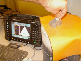
Phased Array can offer cross-sectional imaging of filters from either sectorial or linear scans. This can aid operator visualization of flaws. Automated testing has also been implemented using larger array probes and specialized fixturing. |
Material didáctico
Notas de aplicación
Regresar al material didáctico
Cracking in Ceramic Diesel Particulate Filters
Productos para la aplicación
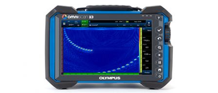
Cada detector de defectos de la serie OmniScan™ X3 es una completa caja de herramientas por ultrasonido multielemento (Phased Array). Las innovadoras y avanzadas técnicas TFM y PA permiten identificar defectos con confianza, mientras que las potentes herramientas de software y los sencillos flujos de trabajo mejoran su productividad.
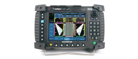
El OmniScan PA efectúa inspecciones manuales y automáticas por ultrasonido multielemento (Phased Array). Ofrece representaciones de pantalla completa para A-scan, B-scan, S-scan y C-scan, y un procesamiento de datos avanzado en tiempo real. Puede ser configurado con 16:128 elementos, 16:16M, 16:64M, 32:32, y 32:128.
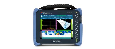
Este equipo ligero de un solo canal proporciona una pantalla táctil fácil de leer de 8,4" (21,3 cm) y soluciones bastante rentables en el plano precio-rendimiento. Viene en dos modelos: SX PA y SX UT. El modelo SX PA es una unidad 16:64PR que, al igual que el modelo SX UT [con un solo canal UT], también está equipado con una canal UT para inspecciones de pulso-eco (pulse-echo), emisión-recepción (pitch-catch) y TOFD.
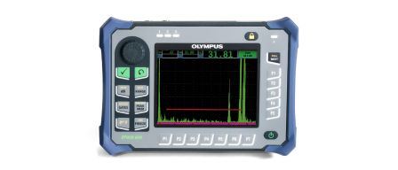
El EPOCH 650 es un detector de defectos por ultrasonido convencional con una excelente capacidad de inspección y utilidad para una amplia variedad de aplicaciones. Este equipo resistente y fácil de comprender es la continuación del reconocido detector de defectos EPOCH 600 y cuenta una variedad de características adicionales.
Lo sentimos, la página solicitada no se encuentra disponible en su país.
Let us know what you're looking for by filling out the form below.