In diesem Anwendungsbeispiel wird erläutert, wie die Wanddicke von hohlen Turbinenschaufeln aus Metall gemessen wird.
Wanddicke der Turbinenschaufel
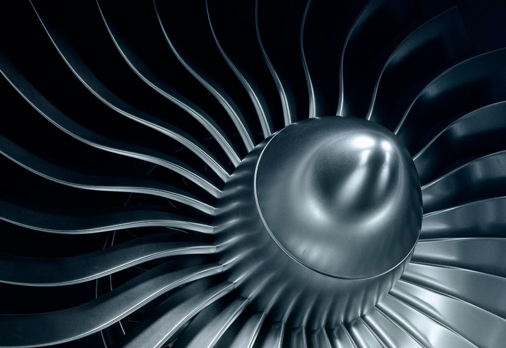
Viele Turbinenschaufeln, die in Flugzeugtriebwerken und anderen Hochleistungssystemen verwendet werden, sind hohl, um die Zirkulation von Kühlmittel innerhalb der Schaufel zu ermöglichen. Kernversätze während des Gießens, fehlerhafte Bearbeitung oder normaler Oberflächenverschleiß während des Betriebs können dazu führen, dass die Wanddicke der Schaufel unter akzeptable Grenzwerte fällt. Ohne die Schaufel zu zerstören, ist eine mechanische Wanddickenmessung in der Regel nicht möglich. Mit geeigneten Messköpfen und Geräten kann diese Messung jedoch oft mit Ultraschall durchgeführt werden.
Ultraschallgeräte zur Messung der Wanddicke von Turbinenschaufeln
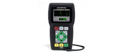
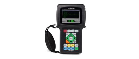
Präzisionsdickenmesser werden häufig zur Messung von Turbinenschaufeln verwendet. Dazu gehören die Dickenmesser 38DL PLUS und 45MG mit Einzelschwinger-Software und Wellenformanzeige als Optionen. Sie werden typischerweise mit Tauchtechnik- oder Vorlaufstreckenmessköpfen verwendet, die entsprechend der zu messenden Dicke und Geometrie ausgewählt werden. Anhand der Wellenformanzeige des Dickenmessers kann ein geschulter Bediener, Wellenformen überwachen, um eine gültige Echoerkennung sicherzustellen. Sie trägt auch dazu bei, eine optimale Messkopfausrichtung zu gewährleisten.
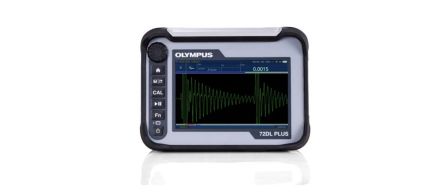
Der 72DL PLUS Dickenmesser ist ein Hochgeschwindigkeitsgerät, das schnelle Messungen während der Herstellung und Prüfung von Turbinenschaufeln bietet. Der Dickenmesser verfügt über eine 60 Hz Anzeigeaktualisierungsrate und Messgeschwindigkeiten von bis zu 2 kHz. Das Gerät verfügt zudem über einen großen 7-Zoll-Touchscreen, der aus verschiedenen Blickwinkeln hervorragend abgelesen werden kann. Mit verschiedenen Verbindungsoptionen (WLAN, Bluetooth und Ethernet) und Datenverwaltungsfunktionen kann der Dickenmesser 72DL PLUS Prüfabläufe optimieren und den Durchsatz verbessern.
Verfahren zur Dickenmessung von Turbinenschaufeln
Das genaue Messsystem, das für eine bestimmte Turbinenschaufelanwendung empfohlen wird, hängt von den Kundenanforderungen und den akustischen Eigenschaften der Schaufel ab. Folgendes sollte berücksichtigt werden:
Messkopftyp: Vorlaufstrecken- und Tauchtechnikmessköpfe werden für Turbinenschaufelanwendungen verwendet. Die Krümmung kleiner Turbinenschaufeln kann es jedoch unmöglich machen, Vorlaufstreckenmessköpfe richtig an die konkave Seite anzukoppeln. Die 3 mm (0,125 Zoll) Vorlaufstreckenmessköpfe (M203 und M208) lassen sich allgemein gut an konkave Radien bis ca. 100 mm (4 Zoll) ankoppeln. Dank der Krümmung der Vorlaufstreckenmessköpfe können sie teilweise an engere Radien angekoppelt werden. Doch allgemein werden stark gekrümmte Oberflächen, insbesondere die Vorderkante von Schaufeln, besser mit Tauchtechnikmessköpfen gemessen. Der 20 MHz Messkopf V316-B in einem B-120 Wassersprudler bietet eine praktische handgehaltene Einheit für die Tauchtechnikmessung von Schaufeln. In vielen Fällen kann auch ein fokussierter V260-SM Sonopen Vorlaufstreckenmesskopf zum Ankoppeln auf konkave Oberflächen verwendet werden, die mit herkömmlichen Vorlaufstrecken nicht gemessen werden können.
Zusätzlich zu der Standardserie der Tauchtechnik- und Vorlaufstreckenmessköpfe bieten wir drei spezielle 20 MHz Vorlaufstreckenmessköpfe mit niedriger Höhe für die Dickenmessung von Turbinenschaufeln in Baugruppen mit mehreren Schaufeln, bei denen der Abstand zwischen den Schaufeln begrenzt und der Zugang schwierig ist. Der M2054 ist ein 20 MHz Vorlaufstreckenmesskopf mit einer Dicke von nur 6,75 mm (0,27 Zoll) und einer Grifffläche von 75 mm (3 Zoll). Der M2055 ähnelt einer Messkopf-Vorlaufstrecken-Baugruppe mit einer Dicke von 10 mm (0,40 Zoll). Der V2034 Vorlaufstreckenmesskopf hat einen 10 mm (0,40 Zoll) Kopf an einem abgewinkelten Griff von 300 mm (6 Zoll). Umrisszeichnungen dieser Messköpfe sind auf Anfrage erhältlich.
Messmodus: Mit Vorlaufstrecken- und Tauchtechnikmessköpfen können Dickenmessungen in Modus 2 (Grenzfläche zum ersten Rückwandecho) oder in Modus 3 (Echo-zu-Echo nach Grenzfläche) durchgeführt werden. Modus 3 bietet eine bessere Auflösung bei dünneren Materialien als Modus 2. Er ist jedoch nur möglich, wenn die zu messenden Punkte von der Turbinenschaufel mehrere Rückwandechos erzeugen. Wenn nur ein einziges verwendbares Rückwandecho vorhanden ist (aufgrund von Krümmung oder Schalldämpfung), muss die Messung in Modus 2 durchgeführt werden. Die Dickenmesser 38DL PLUS und 45MG können in Modus 2 oder Modus 3 eingesetzt werden. Erstellen Sie die optimale Einstellung für eine bestimmte Anwendung für Turbinenschaufeln unter Verwendung von Referenzstandards mit dem Bereich der zu messenden Dicke und Geometrie.
Dickenbereich: Bei typischen Metallschaufeln beträgt die kleinste auflösbare Dicke für einen 20 MHz Vorlaufstrecken- oder Tauchtechnikmesskopf etwa 0,15 mm (0,006 Zoll) in Modus 3 und 0,5 mm (0,020 Zoll) in Modus 2. Für dünnere Materialien unter 0,15 mm kann das Hochfrequenzmodell des 72DL PLUS Dickenmessers verwendet werden. Die meisten Messungen von Turbinenschaufeln werden bei 10 MHz oder 20 MHz durchgeführt.
Tote Punkte: Hohle Turbinenschaufeln enthalten oft verschiedene Strukturen innerhalb der Schaufel, um den Kühlmittelfluss zu lenken oder der Schaufel Festigkeit zu verleihen. Allgemein ist es nicht möglich, ein Rückwandecho von Punkten zu erhalten, an denen sich diese Leitschaufeln oder Rippen befinden, da die Struktur die glatte Innenfläche stört, die für eine gute Reflexion erforderlich ist. In Fällen, in denen diese Strukturen eng beieinander liegen, erzeugt ein fokussierter Tauchtechnikmesskopf mit einer kleinen Ankoppelfläche bessere Rückwandechos als ein Vorlaufstreckenmesskopf. In anderen Fällen kann eine sich stark verjüngende Schaufeldicke dazu führen, dass die Innen- und Außenwand nicht parallel ist, was Echoverzerrungen und potenzielle Messfehler verursachen kann.
Legen Sie immer die Kombination aus Messkopf und Gerät basierend auf den Messungen mit tatsächlichen Prüfteilmodellen fest. Durch die großen Abweichungen der Geometrie der Turbinenschaufeln ist die Prüfteilbewertung wichtig.
Die Abbildungen 1–3 zeigen typische Wellenformen im Zusammenhang mit Messungen von Turbinenschaufeln, die mit einem 38DL PLUS Dickenmesser durchgeführt wurden. Das Display des Dickenmessers liefert sofort das Live-A-Bild mit Blenden und Dickenmesswerten. Dies ist ideal für schwierige Anwendungen oder wenn Konfigurationsparameter genauer betrachtet werden müssen.
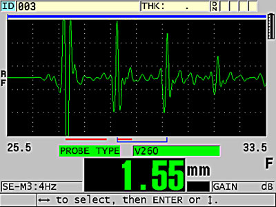
Abbildung 1: Modus 3 Messung einer Turbinenschaufel
Abbildung 1 zeigt eine Messung in Modus 3 einer 1,05 mm (0,041 Zoll) dicken konkaven Kante einer Turbinenschaufel unter Verwendung eines M208 Messkopfs. Die Krümmung hat am Messpunkt einen ausreichend großen Radius, sodass sich der M208 Messkopf gut an das Material ankoppeln lässt und die sauberen Mehrfachechos eine Messung in Modus 3 zulassen.
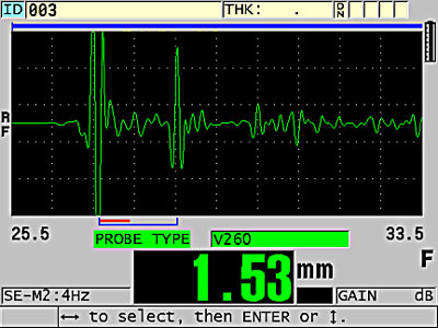
Abbildung 2: Modus 2 Messung einer Turbinenschaufel
Abbildung 2 zeigt eine Messung in Modus 2 einer 1,8 mm (0,070 Zoll ) dicken konvexen Turbinenschaufelwand, auch unter Verwendung eines M208 Messkopfs. Hier dämpfen die vorhandenen Rippen im Inneren die Echos etwas, und durch das Fehlen von sauberen Mehrfachechos wird eine Messung in Modus 2 empfohlen.
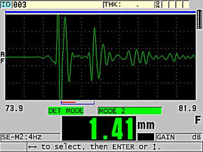
Abbildung 3: Tauchtechnik zur Messung des gekrümmten konvexen Schaufelabschnitts
Abbildung 3 zeigt eine Tauchtechnik unter Verwendung eines V316-BB 20 MHz Tauchtechnikmesskopfs mit einem B-120 handgehaltenen Wassersprudler, um einen dickeren (1,3 mm bzw. 0,051 Zoll) scharf gekrümmten (25 mm bzw. 1 Zoll Radius) konvexen Schaufelabschnitt zu messen, wo die enge konvexe Krümmung das Ankoppeln eines Vorlaufstreckenmesskopfs erschwert. Bei dieser Art von Messung, insbesondere auf konkaven Oberflächen, ist es für den Bediener unerlässlich, die Wellenformen zu überwachen, um eine optimale Messkopfausrichtung sicherzustellen.
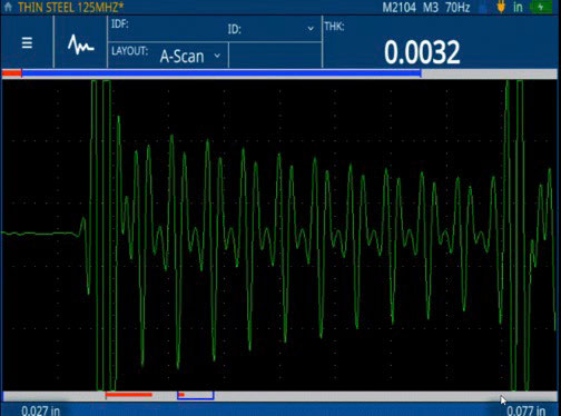
Abbildung 4: Messungen der dünnen Dicke (0,0032 Zoll) von dünnem Stahl mit dem 72DL PLUS Dickenmesser
Abbildung 4 zeigt einen M2104 125 MHz Messkopf mit direktem Kontakt auf einer 0,076 mm (0,0032 Zoll) dünnen Metallscheibe und demonstriert die Fähigkeit des 72DL Plus Dickenmessers zur Messung der Mindestdicke. Ein komplettes Sortiment an Hochfrequenz-Messköpfen von 30–125 MHz ist zur Verwendung mit dem 72DL PLUS Dickenmesser für eine Vielzahl von Dünnschichtanwendungen erhältlich.
Anmerkung: Bestimmte Turbinenschaufeln aus grobkörnigen Legierungen können aufgrund der anisotropen Korngefügestruktur erhebliche Geschwindigkeitsschwankungen von Punkt-zu-Punkt aufweisen. In diesen Fällen wird die Genauigkeit der Ultraschall-Dickenmessung durch den Grad der Geschwindigkeitsvariation begrenzt. Dieser Grenzwert muss im Einzelfall durch Ausprobieren ermittelt werden.