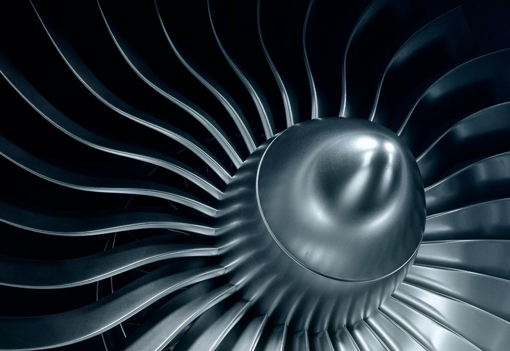
Questa nota applicativa descrive come misurare lo spessore della parete di pale cave di metallo di turbine.
Spessore della parete di pale di turbine
Numerose pale di turbine usate nei motori di aerei e di altri sistemi a alte prestazioni sono cave per consentire la circolazione di liquidi refrigeranti all'interno della pala. Spostamenti della parte centrale dello stampo durante il processo di pressofusione, trattamenti imprecisi o normali fenomeni di usura superficiale possono causare un assottigliamento dello spessore della parete della pala al di sotto di limiti accettabili. La misura meccanica dello spessore della pala non è in genere possibile senza effettuare il sezionamento della pala. Tuttavia attraverso strumenti e trasduttori idonei questo tipo di misura può essere realizzata mediante gli ultrasuoni.
Strumenti a ultrasuoni usati per misurare lo spessore della parete di pale di turbine
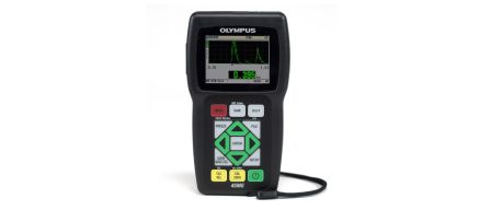
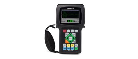
I misuratori di spessore di precisione sono usati comunemente per le misure di pale di turbine. Questi includono il misuratore 38DL PLUS™ e il misuratore 45MG con il software Single Element e l'opzione di visualizzazione della forma d'onda. Sono in genere usati con trasduttori a immersione o a linea di ritardo scelti in base allo spessore e alla forma misurati. La visualizzazione della forma d'onda del misuratore permette a un operatore formato di monitorare le forme d'onda per assicurare un efficace rilevamento degli echi. Inoltre facilita un ottimale allineamento del trasduttore.
Il misuratore 72DL PLUS™ è uno strumento a alta velocità che permette di eseguire delle veloci misure per la produzione e l'ispezione di pale di turbine. Il misuratore offre un aggiornamento del display di 60 Hz e una velocità di misura massime di 2 kHz. Inoltre lo strumento integra un ampio display touch screen da 7" che consente un'ampia visione da diversi angoli. Attraverso diverse opzioni di connessione (wireless LAN, Bluetooth® e Ethernet) e strumenti di gestione di dati, il misuratore 72DL PLUS ottimizza i flussi di lavoro di ispezione e migliora la produttività.
Procedura di misura dello spessore della parete di pale di turbine
Il sistema di misura consigliato per una determinata applicazione di pale di turbine dipende dalle esigenze del cliente e dalle proprietà acustiche delle pale. Di seguito vengono riportate alcune considerazioni essenziali:
Tipo di trasduttore: Per le applicazioni di turbine di pale vengono usati trasduttori a immersione e a linea di ritardo. Tuttavia la curvatura di pale di turbine di ridotte dimensioni potrebbero impedire il corretto accoppiamento dei trasduttori a linea di ritardo sul alto concavo. I trasduttori a linea di ritardo da 3 mm (0,125 in.) (M203 e M208) in genere si accoppiano correttamente con concavità con raggi di curvatura minimi di 100 mm (4 in.). Attraverso la sagomatura della linea di ritardo è possibile, in alcuni casi, realizzare l'accoppiamento con raggi di curvatura inferiori. Tuttavia, in termini generali, le superfici con raggi di curvatura stretti (es: bordi di attacco delle pale) sono misurati con più efficacia attraverso i trasduttori a immersione. Il trasduttore V316-B da 20 MHz in un bubbler B-120 rappresenta una pratica unità palmare per la misura con trasduttori a immersione di pale. In molti casi è inoltre possibile usare il trasduttore a linea di ritardo V260-SM Sonopen™ per accoppiarlo a una superficie concava che non può essere misurata con delle classiche linee di ritardo.
Oltre alla linea standard di trasduttori a linea di ritardo e ad immersione, offriamo tre speciali trasduttori a linea di ritardo da 20 MHz a basso profilo per le misure di spessori di pale di turbine in gruppi di pale multiple dove lo spazio tra le pale è limitato e risulta difficile l'accessibilità. L'M2054 è un trasduttore a linea di ritardo da 20 MHz di appena 6,75 mm (0,27 in.) di spessore con un'impugnatura di 75 mm (3 in.). L'M2055 è simile con un gruppo trasduttore-linea di ritardo spesso 10 mm (0,40 in.). Il trasduttore a linea di ritardo V2034 ha una testa di 10 mm (0,40 in.) su un impugnatura angolata di 300 mm (6 in.). Gli schemi dei trasduttori sono disponibili su richiesta.
Modalità di misura: Utilizzando i trasduttori a linea di ritardo e ad immersione, le misure di spessori possono essere realizzate in Modalità 2 (dall'eco d'interfaccia alla prime eco di fondo) o Modalità 3 (da eco a eco seguendo l'interfaccia). La Modalità 3 fornisce una migliore risoluzione su componenti sottili rispetto alla Modalità 2, tuttavia questo risulta possibile solo se i punti da misurare sulla pala della turbina produce echi di fondo multipli. Se a causa della curvatura o dell'attenuazione può essere utilizzato una sola eco di fondo, la misura deve essere realizzata in Modalità 2. I misuratori 38DL PLUS e 45MG possono funzionare in Modalità 2 o Modalità 3. Per stabilire la configurazione ottimale per una determinata applicazione per pale di turbine è necessario utilizzare campioni di riferimento con intervalli di spessori e forme equivalenti a quelle da misurare.
Intervallo di spessori: In pale di metallo lo spessore minimo misurabile per un trasduttore a immersione o a linea di ritardo da 20 MHz è approssimativamente di 0,15 mm (0,006 in.) in Modalità 3 e di 0,5 mm (0,020 in.) in Modalità 2. Per componenti più sottili, inferiori a 0,15 mm, può essere usata la versione a alta frequenza del misuratore 72DL PLUS. La maggior parte delle misure di pale di turbine sono realizzate a 10 MHz o 20 MHz.
Punti morti: Le pale delle turbine cave spesso contengono delle strutture articolate all'interno delle pale per orientare il flusso di refrigerante o per rafforzare le pale. In genere non è possibile acquisire un'eco di fondo da punti dove sono presenti diaframmi o costolature, visto che queste strutture interrompono la continuità superficiale che permette di assicurare una riflessione ottimale. Nei casi in cui le strutture sono ravvicinate, un trasduttore a immersione focalizzato con una dimensione ridotta del punto di contatto produce degli echi di fondo migliori rispetto a un trasduttore a linea di ritardo. Inoltre esistono dei casi in cui con lo spessore di pale estremamente affusolate si abbiano le pareti interne e esterne non parallele, causando potenzialmente distorsioni dell'eco e errori di misura.
In tutti i casi, è necessario determinare l'ottimale combinazione trasduttore-strumento attraverso test che implicano l'impiego di campioni riferibili al prodotto in oggetto. La significativa variabilità delle forme delle pale di turbine rende basilare la valutazione dei campioni.
Le Figure 1–3 mostrano delle tipiche forme d'onda associate a misure di pale di turbine eseguite con un misuratore 38DL PLUS. La schermata del misuratore visualizza istantaneamente la forma d'onda a ultrasuoni in tempo reale con i gate e le misure di spessore. Questa funzionalità è ideale per le applicazioni complesse o quando i parametri di configurazione necessitano un'analisi più approfondita.
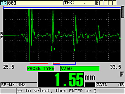
Figura 1. Misura in Modalità 3 di una pala di turbina
La Figura 1 mostra la misura in Modalità 3 del bordo di uscita di una pala di turbina concava di spessore pari a 1,05 mm (0,041 in.) utilizzando un trasduttore M208. La curvatura ha un raggio sufficientemente ampio nel punto di misura da permettere al trasduttore M208 di accoppiarsi in modo ottimale alla componente e i nitidi echi multipli consentono una misura in Modalità 3.
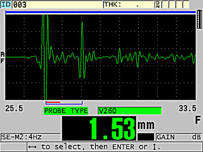
Figura 2. Misura in Modalità 2 di una pala di turbina
La Figura 2 mostra la misura in Modalità 2 della parete di una pala di turbina convessa di spessore pari a 1,8 mm (0,070 in.) utilizzando un trasduttore M208. In questo caso, la presenza di costolature interne attenua in parte gli echi. Inoltre per l'assenza di nitidi echi multipli si consiglia la misura in Modalità 2.
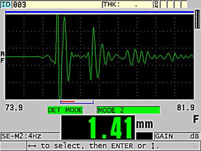
Figura 3. Tecnica ad immersione per misurare la sezione di pala convessa curva
La Figura 3 mostra una tecnica a immersione mediante un trasduttore a immersione V316-BB da 20 MHz con un bubbler B-120 palmare per controllare una sezione di pala con curva convessa a raggio di curvatura stretto (25 mm o 1 in. di raggio) e di maggiore spessore (1,3 mm o 0,051 in.), dove la curva convessa a raggio di curvatura stretto non permette un ottimale accoppiamento del trasduttore a linea di ritardo. In questo tipo di misura, specialmente nel caso di superfici concave, è essenziale per l'operatore poter monitorare le forme d'onda per facilitare un ottimale allineamento del trasduttore.
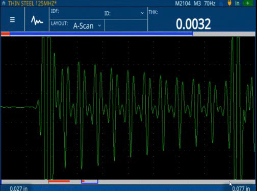
Figura 4: Misure di spessore sottili (0,076 mm [0,0032 in.]) di componenti di acciaio sottili eseguite con il misuratore 72DL PLUS.
La Figura 4 mostra un trasduttore a contatto diretto M2104 da 125 MHz su una sottile zeppa di metallo di 0,076 mm (0,0032 in.) mostrando la capacità di misura degli spessori minimi del misuratore 72DL PLUS. È disponibile una linea completa di trasduttori a alta frequenza compresa tra 30 e 125 MHz da utilizzare in combinazione con il misuratore 72DL PLUS per diverse applicazioni di misura di spessori sottili.
Nota: In alcune pale di turbine costituite da leghe con grani di grandi dimensioni può emergere una rilevante variazione della velocità da punto a punto a causa della struttura dei grani anisotropica. In questi casi, la precisione della misura di spessori a ultrasuoni sarà limitata dal grado di variazione della velocità. Questo limite deve essere determinato sperimentalmente per casi specifici.