缝隙腐蚀是一种我们已经了解的使材料受到损坏的机理。缝隙腐蚀的机理如下:出现在材料某个特定部位上的一些腐蚀 性物质,或者混合在一起的几种物质,会形成某种腐蚀性溶液,并加速材料的损坏进程。缝隙腐蚀的一个示例是发生在 两个相对法兰的密封面之间的腐蚀,两个法兰的密封面之间有一个垫圈。
腐蚀性物质会在缝隙中存留,例如:密封面与垫圈材料之间的缝隙。腐蚀性材料在局部区域聚集,就会加速腐蚀的进 程。密封区域受到腐蚀或者缺失,会使密封状态不复存在,并释放出会引起灾难性事故的物质,造成资产损失、生产停 滞,甚至造成人员伤害。
对法兰的密封面进行检测已经成为一种标准惯例。对法兰 的密封面进行原位检测是运行和维护程序的一个环节。预 紧是一种常见的测试手段,以确定需要对哪个法兰进行修 理。 发现问题后,在现场对法兰面进行机加工,是一种原位检 修的方式。可以使用超声检测方法确定是否已经对法兰面 进行了机加工修理,或者确定是否出现了密封面缺失的情 况。如果法兰密封面已经无法修复,则需要更换法兰,或 者需要使用堆焊技术重塑密封面。 | 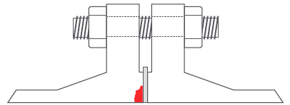 凸面法兰的横截面图 |
注意:如果法兰面已经通过焊接和机加工方式得到修复,则超声(UT)检测可能会将检测到的焊接区域判定为一个界面。 由于将修复密封面的信号误认为是界面的信号,因此可能会得出密封区域缺失的错误判断。
相控阵检测应用
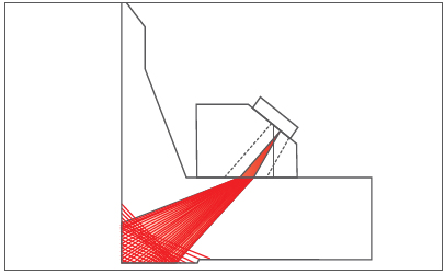
最常放置超声检测探头的两个位置是法兰的斜面区域和螺栓孔之间的区域,如下面的图片所示。
法兰的斜面区域并不总是相同,因此必须为每个法兰单独绘制几何图形。这个步骤比较困难,而且会导致在法兰状况的评估方面出现错误。
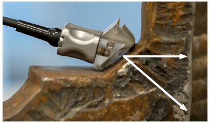 相控阵探头被放置在法兰的斜面区域。 | 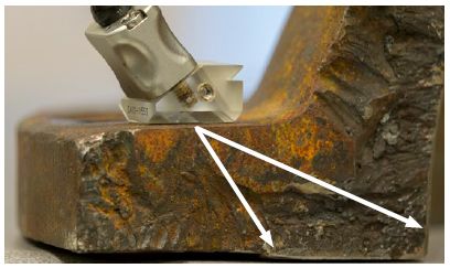 相控阵探头被放置在螺栓孔之间的区域。 |
凸面法兰的图片
下面的图片表明一个应用于管道的凸面法兰的示例。
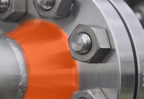 相控阵探头可以被放置在法兰的斜面区域。 |  相控阵探头可以被放置在螺栓孔之间的区域。 |
来自Eclipse Scientific的BeamTool软件
BeamTool软件有助于更方便地设置相控阵技术。
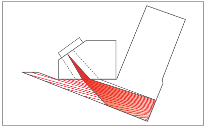 相控阵技术被应用到放置在法兰斜面上的探头。 | 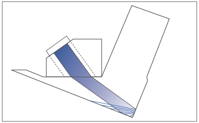 |
 相控阵技术被应用到放置在螺栓孔之间的探头。 | 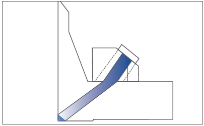 |
工业应用
这种检测应用的主要用户是氢氟酸(HF)的制造商和/或用户。氢氟酸装置常见于精炼厂和化工厂。其它工艺类型也会破坏法兰的密封面,如:酸、蒸汽和盐水。
用于校准的标准样件在检测之前,应该使用一个校准样件对相控阵的设置进行确认。用于校准的标准样件是一个大小和重量都与被检法兰相同的法兰,这个法兰的凸面密封区域中制造了一些可能会出现在实际被检法兰中的缺陷。使用相控阵设置对这个法兰进行检测,可以最终确认相控阵设置的检测性能。 一个标准校准样件示例的目标缺陷如下: A = 0.075英寸深 × 1.0英寸长 | 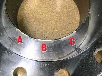 |
适用的奥林巴斯产品
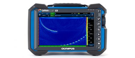
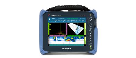
使用EPOCH® 1000, OmniScan® MXU-M, OmniScan SX, OmniScan MX2, 或OmniScan MX探伤仪可以对凸面法 兰进行检测。
奥林巴斯的小型相控阵探头非常适用于检测螺栓和螺母之间距离较小的法兰。
优势特性
- 无需拆分法兰,就可以对密封区域的状态进行评估
- 为业主/操作人员节省了成本
- 无需拆分法兰,就降低了操作人员接触危险化学品的可能性,从而增加了生产和检测的安全性
- 可以在线检测设备
- 在TAR开始之前,制定维修计划