7.6 Fiberglass and Composites

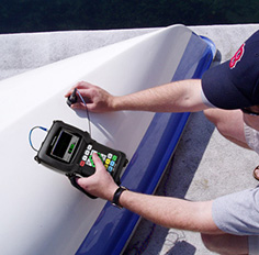
Ultrasonic flaw detection is not limited to metals. As the use of fiberglass and composites in manufacturing has increased in recent years, so has the need to inspect these materials for structural flaws such as delaminations and impact damage. Both problems can usually be identified through ultrasonic testing. Major users include the aerospace, wind power, marine, and automotive industries as well as manufacturers of fiberglass tanks and other structures.
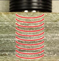
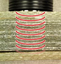
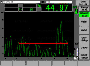
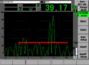
Low frequency straight beam transducers (2.25 MHz, 1 MHz, and often 500 KHz)) are normally used for testing fiberglass due to its often high degree of sound scattering. Thicknesses of 75 mm (3”) and greater can typically be tested with appropriate transducers and instrument setups. In most cases the procedure involves identifying the backwall echo from the test piece and then looking for indications appearing ahead of the backwall. Scatter noise will commonly be present, so detectable laminar flaws will be those whose echo response is greater than the background scatter. The example below shows a test of a 45 mm (1.78”) fiberglass plate. The waveform at left shows a backwall echo towards the right side of the screen. In the waveform at right, the large indication at 39 mm depth comes from the visible delamination. All other peaks represent internal scattering.
 |  |
 |  |
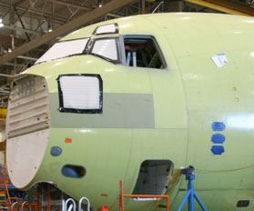
Carbon fiber composites are usually more transmissive than fiberglass and so they can be tested at frequencies up to 5 MHz for better resolution of laminar defects near the front and back surfaces. This is important in applications like detection of impact damage in aircraft parts, where solid laminate aircraft composites can be internally damaged by impacts in a way that is not visible on the outer surface. The example below shows detection of an inserted artificial disbond in a 3.5 mm (0.140”) graphite/epoxy aircraft panel. The insert is located less than 0.5 mm from the backwall but it can be identified in this test with a 5 MHz broadband delay line transducer as a small shift in the position of the echo.
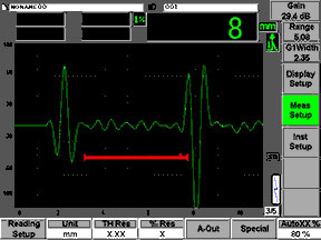 |  |
| Backwall echo to right of gate | Laminar defect echo in gate |
Honeycomb composites are more challenging because of the large amount of air contained in them. Through transmission testing with conventional transducers can detect skin separation and core damage, however this is typically done by automated scanning systems at the manufacturing stage and is not a practical field test. But there are also advanced methods for one-side ultrasonic testing of carbon fiber as well as honeycomb composites, including resonance testing, mechanical impedance testing, and Lamb wave pitch/catch testing. In the case of honeycomb, both skin separation and crushed cores can be identified from one side of the part. These advanced methods required specialized equipment such as the Olympus NDT Bondmaster. Detailed information on these methods can be found at this link.