Proceedings of ASME PVP Conference: | |||||||||||||||||||||||||||||||||||||||||||||
Abstract | |||||||||||||||||||||||||||||||||||||||||||||
Pipelines are now using Fitness-For-Service (FFS) for accept/reject of weld defects. FFS requires accurate measurement of defect height for Fracture Mechanics assessments. The standard pipeline weld inspection technique of radiography is incapable of such measurements. However, the newer technique of ultrasonics can measure defect height, in principle. Initially ultrasonic amplitude methods were used for height measurement, but these proved unreliable. Now diffraction methods, especially Time-Of-Flight- Diffraction (TOFD), are being used in conjunction. This paper reviews previous work - mainly large nuclear studies like PISC II - and published pipeline sizing studies. The best nuclear sizing was within a few millimetres, using diffraction. In contrast to nuclear, pipeline AUT uses zone discrimination, focused transducers, much thinner material and simpler analysis techniques. Current accuracies are typically + 1 mm (terminology undefined), which correlates with the beam spot size and typical weld pass. Requests for accuracies of + 0.3 mm are probably unachievable, though future R&D should significantly improve pipeline sizing. | |||||||||||||||||||||||||||||||||||||||||||||
Introduction | |||||||||||||||||||||||||||||||||||||||||||||
Defects invariably occur from welding, even with the most stringent procedures. In practice it is not practical to remove all defects by repair, so some acceptance criteria must be used to determine which defects should be removed and which left in place. This situation has become even more important with the advent of high strength steels, where grinding and rewelding typically destroy the controlled microstructure; repair may create more damage than leaving the defect in. In the last decades, there has been a move away from "workmanship" criteria, where defects were accepted or rejected primarily on what the inspection system could detect, to "Fitness-For-Service" (FFS) criteria, which are based on Fracture Mechanics (also called Engineering Critical Assessment, or ECA). FFS uses the material toughness, crack growth data and the component duty cycle to estimate the service life, and hence acceptable initial defect size. Conservatism is built into the calculations by giving error margins to the inputs: toughness, growth rates and defect measurements. Typically, FFS permits much larger defects than workmanship criteria, which reduces reject rates and costs. However for FFS, it is essential to accurately and reliably measure the key defect parameter: defect height. In the 1980s, nuclear was the leading industry investigating defect sizing, with FFS starting in this industry. Since the arrival of automated ultrasonics in the gas pipeline industry [1], AUT is becoming the inspection method of choice due to FFS. The use of AUT and FFS in the pipeline industry has significantly lowered reject rates (though this is partially due to the ability of AUT to perform process control). For several decades, the prime pipeline weld inspection technique was radiography, based on workmanship criteria. Besides the obvious safety hazards, one major deficiency of radiography is its inability to measure defect height, thereby eliminating FFS as an option. In the last couple of decades, ultrasonics has become more prevalent; ultrasonics does offer the potential of measuring defect height, but this is a difficult measurement in practice, and fraught with errors. There are two main approaches: amplitude-based and diffraction-based. These are discussed below. | |||||||||||||||||||||||||||||||||||||||||||||
Amplitude vs. Diffraction | |||||||||||||||||||||||||||||||||||||||||||||
Amplitude Techniques Perhaps the biggest variable is the defect itself. Ultrasonics is highly sensitive to defect orientation; also, transparency, roughness, curvature, location play a role. Conventional ultrasonics is particularly unreliable for vertical defects, though using appropriate inspection angles seems to improve amplitude criteria [3]. The German DGS technique compares defect amplitudes with those from a known reflector [4]; this gives a defect "not smaller than a machined reflector", which is not useful for FFS. All in all, amplitude-based sizing techniques are generally not reliable, certainly by the standards required by FFS. Since the vast majority of defects are still sized by amplitude-based techniques, whether 6 dB drop-off, 10 dB or 20 dB [5], a couple of general comments from field experts are appropriate. First, "any defect smaller than the beam tends to be sized as the beam width". This occurs because small defects tend to be omni-directional emitters, so small defects tend to emit anywhere inside the beam. However, small defects tend not to be structurally important in most cases, so the background data on small defect sizing is limited [6]. Second, "small defects tend to be oversized, and large defects undersized" [7]. The "small defects-oversizing situation" is easily understood from omni-directional emitting and beam spread. However, the "large defects-undersizing" is of more concern. This situation can easily occur if the defect is curved, for example, so a fixed angle transducer beam will roll off the edges, giving lower amplitude and size measurement. Undersizing large defects is potentially a major concern for structural integrity. Diffraction Approaches Nuclear Sizing Studies There are significant differences between these nuclear studies and current pipeline sizing studies: Pipeline Sizing Procedures and Terminology For analysis procedures, pipeline operators often salami-slice the pipes to get an approximate defect size or freeze-break the welds, unlike the meticulous metallography in PISC II. This inherently leads to some errors in sizing and detection; no hard data is available, but metallurgical errors appear to be of the same order as claimed sizing accuracies. Alternative techniques are freeze-breaking and sectioning at the maximum ultrasonic amplitude (which may not be the maximum depth). Pipeline scans are usually performed once (as in the real world), and detailed scans are not used (unlike nuclear). Pipeline sizing is often based solely on zone size as per the ASTM E-1961 code [16], or a modified version of amplitude sizing [17]. Zone sizing is quick and approximate, not detailed like nuclear. Pipeline defect sizing terminology is fuzzy. Normally defect sizing accuracy is quoted as ± Y mm accuracy. The scientific basis for the ± Y mm is not always specified, but could be: ASME RMS What Do People Really Mean by Sizing Error? Physics Limitations Numerical Focal Spot Size
Battelle PNL Study In 1997, Iploca (International Pipeline and Offshore Contractors Association) funded a detection and sizing study at the University of Ghent [4, 24]. While detection was good by both AUT crews, sizing (by one team only) produced a standard deviation of defect sizing to within + 1.5-2 mm for surface breaking defects. This level of sizing accuracy was later confirmed by similar privately sponsored validation projects [24]. The work done by Ghent University also demonstrated that the sizing error of buried defects can be quite significant. Transco Trials: Recently, Advantica analyzed an internal study using GTI funding with seven inspection companies [25]. Approximately ninety typical defects were implanted: porosity, lack of fusion and both copper cracking and transverse defects. While the main thrust of the trial was defect detection (which was good),the defect sizing was not impressive. σ varied from 1.1 to 1.8 mm [26]. Errors of up to 6 mm were found, while TOFD onlyworked for larger, buried flaws.
Saipem Study ![Cataldo and Legori [28] published a limited data set which shows a good correlation with defect size](https://static1.olympus-ims.com/modules/imageresizer/7bc/40d/d995b904d5/451x316p226x158.gif) One of the more interesting observations is the comparison of conventional multiprobe and phased array AUT systems. When using the same set-up (and nominally the same calibration blocks), the differences are negligible, as predicted by physics. Shell/Shaw [27] used multiprobe; Saipem phased array. Two other comparisons showed no significant detection differences using the same set-ups [25, 29]. Oceaneering OIS EdisonWelding Institute Round Robin Under GTI auspices, EWI performed a round robin with two pipes containing effectively twenty four LoF defects with several inspection companies [21]. The results showed considerable variability between inspection companies, even when using nominally identical procedures. Specifically, in the best case 45% of the defects were sized within + 0.5 mm, and the majority within + 2 mm (see Table 1 below).
Det Norske Veritas  Figure 8: DNV sizing results [22] R/D Tech Data | |||||||||||||||||||||||||||||||||||||||||||||
Discussion | |||||||||||||||||||||||||||||||||||||||||||||
In practice, with the exception of the Oceaneering and EWI results, the available data seems to be fairly self-consistent, with the RMS and σ typically over 1 mm. Much of the data can be overlaid without serious distortion, suggesting that the key issue is technology limits, not operator experience or equipment. Mean error is typically well below 1 mm, with limited undersizing. At this point in time, most evidence suggests that sizing accuracies greater than σ ± 1 mm are not realistic. The proprietary R/D Tech data set suggests that an "eyeball range" of ± 1 mm is really an RMS or standard deviation of <± 1 mm. However, the data is not strictlycomparable since test conditions vary, AUT procedures are not identical, sectioning varies, etc. Generally, mean sizing error is small, typically close to zero mm. Diffraction techniques offer a lot more potential than amplitude techniques, though TOFD in particular has limitations with the smaller defects (and the near surface defects). Relying on amplitude techniques alone will typicallylimit sizing accuracy to the focal spot diameter (~2 mm, or the eyeball range of ± 1 mm as found in recent studies), with frequent outliers. Apportioning amplitudes does not improve σ values much. Undersizing is generally not a major issue. In principle, TOFD should minimize the number of gross overcalls. Current requests for defect sizing to ± 0.3 mm accuracy in plant (again, terminology undefined) seem unrealistic from these published results. There is no evidence that unpublished (or proprietary) results show any significant improvement. On nuclear materials using much shorter λ and perfect geometry, repeatable accuracies of ± 0.1 mm have been achieved [32]. However, such ultrasonic frequencies are impossible in ferritic steels, which are more microstructurally-limited. Though some work has been done on the limits of ultrasonics in steels [33], more should be done specifically on pipeline materials and AUT conditions. From an FFS perspective, the best solution with current technology is to add ± 1 mm to ±1.5 mm to all sizing estimates for conservatism; this should cover any undersizing. For larger defects, the best solution is to use more than one technique to avoid the gross oversizing (5 mm or more) that can occur [22]; typically use zone discrimination, TOFD, back diffraction, and multiple angles [6] if time permits (especiallyfor risers and tendons). Fortunately, work is underway on alternative and improved sizing techniques. R/D Tech is working on a number of fruitful areas: | |||||||||||||||||||||||||||||||||||||||||||||
Conclusions | |||||||||||||||||||||||||||||||||||||||||||||
1. Pipeline AUT defect sizing is becoming more critical with the increasing use of Fitness-For-Purpose, especially for offshore risers and tendons. | |||||||||||||||||||||||||||||||||||||||||||||
Acknowledgements | |||||||||||||||||||||||||||||||||||||||||||||
Mr. Ed Ginzel of Materials Research Institute, Waterloo, Ontario provided valuable advice and assistance. Oceaneering OIS provided proprietary data submitted to DNV. | |||||||||||||||||||||||||||||||||||||||||||||
References | |||||||||||||||||||||||||||||||||||||||||||||
|
[1] Ginzel E.A., 2000, "Mechanized Ultrasonic Inspections of Pipeline Girth Welds - A Brief History", NDT.net, 2000, Vol 5. No. 03,
http://www.ndt.net/article/v05n03/eginzel/eginzel.htm [2] Gruber G.J., G.J. Hendrix and W.R. Schick, 1984, "Characterization of Flaws in Piping Welds using Satellite Pulses", Materials Evaluation, Vol. 42, p. 426. [3] Bray A.V. and R.K. Stanley, 1995, "An Analysis of UT Amplitude Comparison Flaw Sizing and Dissection Results in Steel Pipe", NDE-Vol 13, NDE for the Energy Industry, ASME, p. 85. [4] Dijkstra F.H., J. v.d. Ent and T.J. Bouma, 2000, "Defect Sizing and ECA: State of the Art in AUT", Pipeline Technology Conference, Brugges, 21-24 May. [5] Ismail M.P. and A.B. Muhammad,1998, "Defect sizing by ultrasonic ANDSCAN", Insight vol. 40, no. 11, p. 769. [6] Murphy R.V., 1987, "Ultrasonic Defect-Sizing using Decibel Drop Methods, Vol 1: Text", Atomic Energy Control Board Project No. 85.1.9, Canada. [7] PISC, 1997, Welding Research Council Bulletin 420, Abstracted by S.H. Bush, Ch. 7. [8] Silk M.G., 1979, "Defect Sizing using Ultrasonic Diffraction", British Journal of NDT,, p. 12. [9] Charlesworth J.P. and J.A.G. Temple, 1989, "Ultrasonic Time of Flight Diffraction", Research Studies Press. [10] Adler L., K.V. Cook, H.L. Whaley and R.W. McClung, 1977, "Flaw Size Measurement in a Weld Sample by Ultrasonic Frequency Analysis", Materials Evaluation, p. 44. [11] Schmitz V., W. Müller and G. Schäfer, 1984, "Flaw Sizing and Flaw Characterization with HOLOSAFT", Materials Evaluation, Vol. 42, p. 439. [12] Baby S., T. Balasubramanian and R.J. Pardikar, 2002, "Estimation of the height of surface-breaking cracks using ultrasonic methods", Insight vol. 44 no. 11, p. 679. [13] Jacques F., F. Moreau and E. Ginzel, 2003, "Ultrasonic Backscatter Sizing Using Phased Array -Developments in Tip Diffraction Flaw Sizing", submitted to Insight. [14] Zippel W., J. Pincheira and G.A. Washer, 2000, "Crack Measurement in Steel Plates using TOFD Method", Journal of Performance of Constructed Facilities, p. 75. [15] Highmore P.J., A. Rogerson and L.N.J. Poulter, 1988, "The Ultrasonic Inspection of PISC II Plate 2 by the Risley Nuclear Laboratories", British Journal of NDT, p. 9. [16] ASTM 1998, E 1961-98, "Standard Practice for Mechanized Ultrasonic Examination of Girth Welds Using Zonal Discrimination with Focused Search Units", American Society for Testing and Materials. [17] Gross B., T.S. Connelly, H. van Dijk and A. Gilroy-Scott, 2001, "Flaw sizing using mechanized ultrasonic inspection on pipeline girth welds", NDT.net, Vol. 6, No. 7. [18] ASME, 2001, "Performance Demonstration for Ultrasonic Examination Systems", Appendix VIII, p. 331, American Society of Mechanical Engineers. [19] Kraut E.A., 1976, "Review of Theories of Scattering of Elastic Waves by Cracks", IEEE Transactions on Sonics and Ultrasonics, Vol. SU-23, No. 3, p. 162. [20] Mair H.D., 2003, private communication, 2003. [21] Lozev M., 2002, "Validation of Current Approaches for Girth Weld Defect Sizing Accuracy by Pulse-Echo, Time-Of-Flight Diffraction and Phased Array Mechanized Ultrasonic Testing Methods", EWI Project No. 45066CAP. [22] Förli O., 2002, "Qualification of AUT for Offshore Pipelaying and the Role of NDT", 3rd European-American Conference on NDT Reliability and Demining", Berlin, 10-13 September. [23] Heasler P.G. and S.R. Doctor, 1976, "Piping Inspection Round Robin", NUREG/CR-5068, PNNL-10475. [24] Denys R., T. Lefevre, C. de Jaeger, S. Claessens, 2000, Study on "Weld Defect Acceptance Criteria", Final report for a group of sponsors, Laboratorium Soete, Gent, Belgium, May 2000. [25] Morgan L., 2002, "The Performance of Automated Ultrasonic Testing (AUT) of Mechanised Pipeline Girth Welds", 8th ECNDT, Barcelona. Also, www.ndt.net/article/ecndt02/morgan/morgan.htm [26] Morgan L., P. Nolan, A. Kirkham and P. Wilkinson, 2003, "The use of automated ultrasonic testing (AUT) in pipeline testing", Insight November. [27] Kopp F., G. Perkins, G. Prentice, D. Stevens, 2003, "Production and Inspection Issues for Steel Catenary Risers", Offshore Technology Conference, Houston, 5-8 May 2003. [28] Cataldo G. and R. Legori, 2003, "Advanced Ultrasonic Techniques in Pipeline Girth Welds Examination", ASME PVP-Vol. 456, Paper number PVP2003-1852, p. 49. [29] Sjerve E., D.C. Stewart and G.F. Bryant, "Comparison of Multi-Probe and Phased Array Girth Weld Inspection Systems", IPC 2000, ASME 2000 International Pipeline Conference, Calgary, Alberta, October 1-5, 2000, page 827830. [30] Oceaneering International, 2003, private communication. [31] Förli O., 2003, private communication. [32] Lindenschmidt K. and M. Moles, 1991, "Crack Depth Measurements in Thin-Walled Tubing by Time-Of-Flight", Review of Progress in Quantitative NonDestructive Evaluation, Vol. 11, p. 2093. [33] Mudge P.J., 1981, "Size Measurement and Characterization of Weld Defects by Ultrasonic Testing", Part 3: The effect of metallurgical features in ferritic steels", The Welding Institute Reference 3527/11/81. [34] Honarvar F., T. Dusatko, Y. Fan, F. Farzbod, M. Moles and A.N. Sinclair, 2003, "A novel signal processing technique for enhancement of time-of-flight diffraction (TOFD) signals", ICPIIT VIII, Houston, June 18-21, 2003. [35] GTI, 2003, Gas Technology Institute Project "Control of Horizontal Beam Width with Phased Array Transducers RPTG-0334", by R/D Tech. | |||||||||||||||||||||||||||||||||||||||||||||
Rozwiązania dla przemysłu
Multimedia
Oficjalne dokumenty
Back to Resources
Defect Sizing in Pipeline Welds – What Can We Really Achieve?
 Figure 3: Back diffraction for defect sizing.
![Kopp et al [27] internal study including defect sizing](https://static5.olympus-ims.com/modules/imageresizer/eb5/4c0/c583c84bdd/419x260p210x130.gif)
ProductsUsedApplications
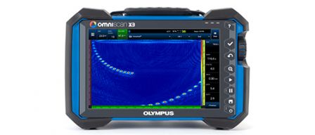
Every flaw detector in the OmniScan™ X3 series is a complete phased array toolbox. Innovative TFM and advanced PA capabilities help you identify flaws with confidence while powerful software tools and simple workflows improve your productivity.
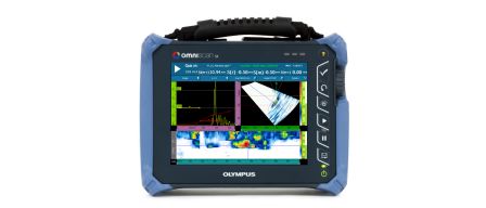
The single group, lightweight OmniScan SX features an easy-to-read 8.4 inch (21.3 cm) touch screen and provides cost-effective solutions. The OmniScan SX comes in two models: the SX PA and SX UT. The SX PA is a 16:64PR unit, which, like the UT-only SX UT, is equipped with a conventional UT channel for P/E, P-C or TOFD inspections.
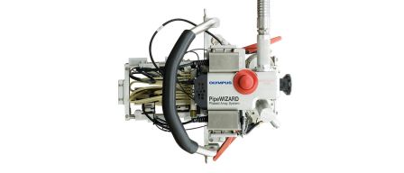
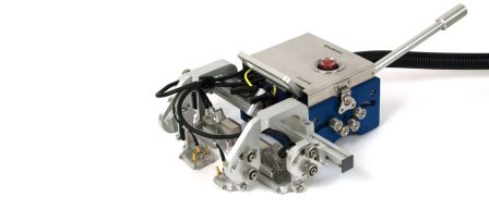
PipeWIZARD to zautomatyzowany system inspekcji spoin obwodowych, w którym wykorzystywana jest technika Phased Array i konwencjonalna technika ultradźwiękowa (AUT). System został zaprojektowany specjalnie z myślą o inspekcji połączeń spawanych w miejscu pracy w ekstremalnych warunkach, na lądzie i na morzu.
WeldROVER to prosty, odporny na warunki przemysłowe, kodowany skaner zmotoryzowany w jednej osi, który umożliwia akwizycję danych we w pełni zautomatyzowany sposób. Umożliwia prowadzenie wydajnej inspekcji spoin na ferromagnetycznych rurociągach lub zbiornikach przy użyciu maksymalnie 6 sond i techniki Phased Array. UT, TOFD, PA.
Sorry, this page is not available in your country
Let us know what you're looking for by filling out the form below.