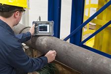
PipeWIZARD™ iX Automated Ultrasonic System for Girth Weld Inspection
The PipeWIZARD™ iX phased array ultrasonic testing system helps pipeline companies ensure the reliable validation of girth welds during the construction process. Equally rugged and compact, the PipeWIZARD iX system is designed to facilitate both onshore and offshore pipeline inspections. A highly efficient automated ultrasonic testing (AUT) solution, this powerful multitechnology detection system reveals defects in girth welds and the heat-affected zone (HAZ) so they can
be quickly analyzed and evaluated.
High-Performance Instrument for Standard and Advanced Inspections
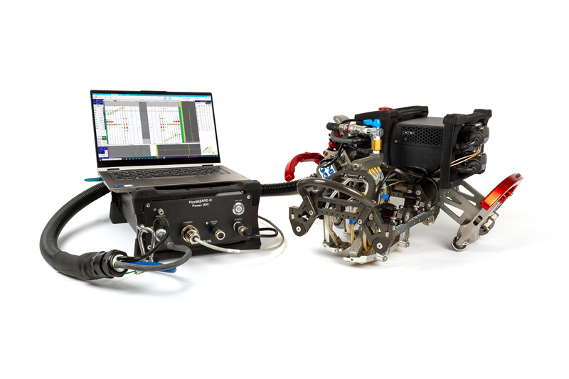
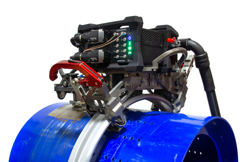
The PipeWIZARD iX system is built to resist vibrations, shocks, and electromagnetic interference, and it can withstand extreme temperatures. Thanks to its compact yet robust design, the PipeWIZARD iX system is also easy to transport and manipulate with confidence.
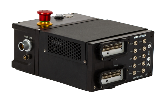
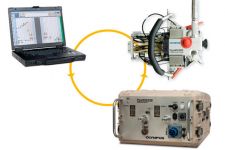
Lighter than its predecessor, the PipeWIZARD iX system’s data acquisition unit is integrated onto the scanner, making it easier to set up and operate. Featuring more powerful electronics and more input channels, the QuickScan iX PA 64:256 data acquisition instrument boosts the PipeWIZARD system’s capabilities and efficiency, improving the coverage capacity and supporting advanced ultrasonic inspection techniques.
Improved Ease of Use and On-Site Efficiency
The optimized hardware design of the PipeWIZARD iX system provides increased setup flexibility and adaptability. Additional umbilical cable lengths, quick-latching connectors, and configurable probe modules increase your ability to accommodate the PipeWIZARD iX setup to varying inspection needs and environments. Its narrower band also significantly reduces coating cutback requirements versus its predecessor.
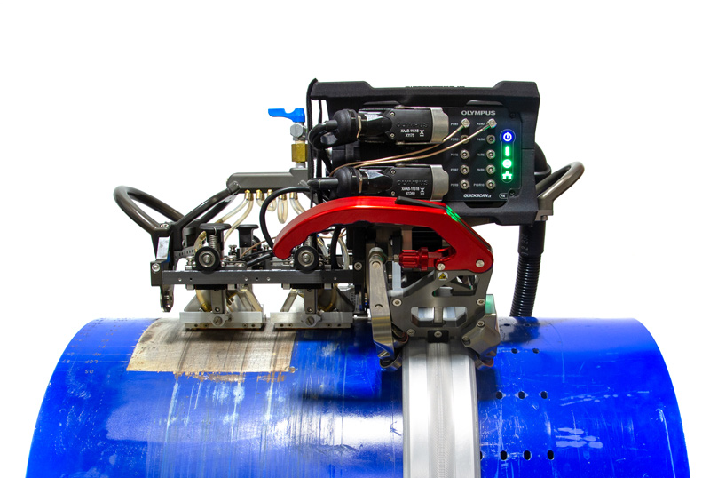
The PipeWIZARD iX system enables onsite inspection personnel to work together more easily and efficiently. Integrated indicator lights and software functions ease the communication between the scanner technician and operator, so the inspection goes smoothly, even under challenging conditions.
Optimized Inspection and Analysis Workflow
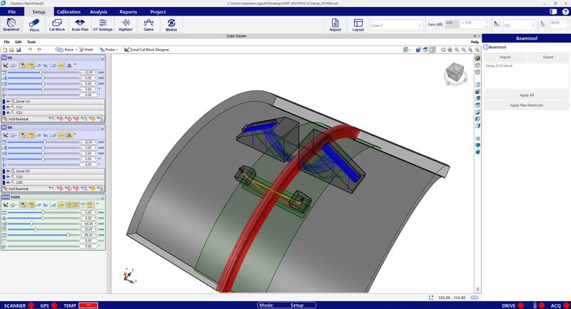
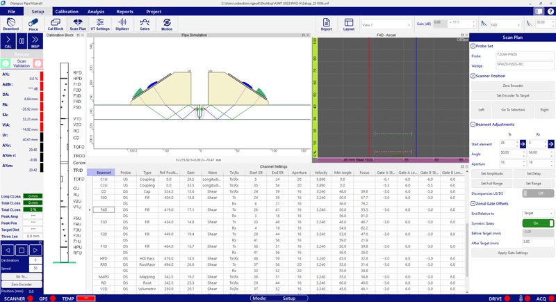
Thoughtfully designed to reflect the key requirements for reliable and code-compliant girth weld validation, the PipeWIZARD iX companion software is easier to use yet features more advanced and sophisticated tools, including:
Embedded ES BeamTool software
Calibration block designer
Encoder auto-calibration
Analysis assistance
For increased data accessibility and versatility, the QuickScan iX PA acquisition unit saves data files in an open file format, facilitating custom software development. If customization is an aspect that interests you, talk to your Evident representative for more details.
Applications
Complete Girth Weld Inspection System
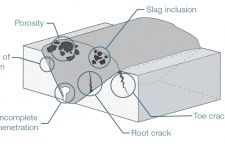
The PipeWIZARD iX girth weld inspection system is built for demanding and extreme conditions, from cold subarctic regions to hot deserts. Detecting defects including lack of fusion, incomplete penetration, porosity, burn through, undercut, hi-low, crack, cold lap, inclusion, etc. the PipeWIZARD iX system adapts to all circumferential weld configurations:
Any weld profile type, including J-bevel, V-bevel, double V, X, etc.
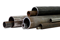
Pipe wall thicknesses typically from 6 mm (0.25 in.) to more than 35 mm (1.4 in.); options are available for thicker pipes.
Pipe diameters from 168 mm (6.625 in.) to 1524 mm (60 in.).
Pipe materials from standard carbon-steel to more complex configurations, including Inconel, and cladded pipe.
Automated Ultrasonic Testing (AUT)
For pipeline girth weld inspection, automated ultrasonic testing (AUT) is the replacement of choice for traditional radiography.
Some clear advantages of AUT over radiography:
No radiation risks for personnel, no chemicals, or environmental concerns
Comparatively short inspection cycle time enabling high productivity
Better detection and sizing accuracy, leading to lower rejection rates
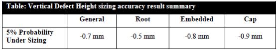
Satisfies Engineering Critical Assessment (ECA) acceptance criteria with measurement of vertical height and depth of indications
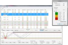
Real-time analysis from smart output display
Data and inspection reports
No licensing required
Multitechnology Inspection Capabilities
Leverage the versatile advanced phased array and conventional ultrasonic technology of the PipeWIZARD iX system:
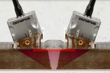
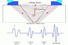
Zone discrimination―each zone, approximately equal to a welding pass, is inspected individually with a PA pulse-echo or pitch-catch technique, enabling full coverage of the bevel area and the volume of the weld with accurate flaw sizing.
Time-of-flight diffraction (TOFD)―used to confirm indications seen on the strip chart or to improve detection and sizing on small or misoriented indications.
Phased array (PA)― conventional PA techniques, such as sectorial, linear, or compound scans, can be used as complementary methods or to inspect weld configurations where zone discrimination is not optimal.
Conventional UT―for detecting transverse flaws in a pitch-catch configuration, measuring wall thickness, inspecting the upper area of the weld with creeping waves, etc.
Total focusing method (TFM) compatible―the powerful QuickScan iX PA data acquisition instrument is capable of supporting the complex firing patterns required for advanced techniques such as TFM.
Code Compliance for Girth Weld AUT Inspections
Confidently validate girth welds according to international standards and regulations governing both the offshore and onshore pipeline industry. The PipeWIZARD iX system enables you to perform AUT inspections that comply with the following codes:
ASTM E-1961 code (covering key elements of AUT of girth welds, including zone discrimination, rapid data interpretation, specialized calibration blocks, and configuration procedures)
API 1104 standard (by inference)
DNV-OS-F101 standard (the offshore AUT code)
When your company’s specifications demand it, you can increase the accuracy of your flaw sizing and achieve a level of resolution that exceeds these code requirements.
Features
Key Features of the PipeWIZARD iX System
Integrated QuickScan iX PA data acquisition instrument accommodating PA probes with up to 256 elements and up to 10 independent UT probes.
Acquisition unit conveniently mounted on the scanner, eliminating signal attenuation due to a long umbilical cable.
Embedded with Eclipse Scientific’s BeamTool software for inspection and analysis, offering the zonal discrimination technique including a zonal cal block designer.
Software equipped more automated tools:
Auto-setup
Auto-layout
Encoder auto-calibration
Assisted analysis
Auto-sizing in height and length
Quick-connect umbilical cable is light, swivels easily, and come in various lengths, simplifying cable management and improving the signal-to-noise ratio (SNR).
Length options: 10 m, 20 m, 30 m, and 50 m (32.8 ft, 65.6 ft, 98.4 ft, and 164 ft).
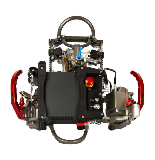
Scanner carriage is easy to set up and operate with its improved clamping and drive wheel adjustment mechanisms, making it easier to adapt to different pipe diameters.
Minimal parts requiring low maintenance and designed for durability in all conditions.
Width of the band is reduced, lowering the required coating cutback (shorter coating cutback than the previous model); the same band can be used for 2 pipe diameters using the optional spacers .
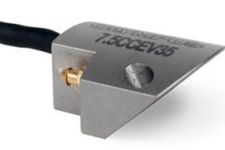
Probe module holds up to 12 probes; you can easily remove and add sections as required.
The smart spring-loaded arms (low maintenance) holding the probes are equipped with a pointer to set accurately the index offsets.
Direct communication between scanner technician and operator (“Ready” button and scan validation light).
GPS option to record geographic position in the data file.
System hardware is ready to support FMC/TFM (upcoming software feature).
Specifications
PipeWIZARD iX System
System Specifications
Size
Full scanner with handles
577 mm × 578 mm × 210 mm (22.7 in. × 22.7 in. × 8.3 in.)
Acquisition unit
243 mm × 188 mm × 100 mm (9.6 in. × 7.4 in. × 3.9 in.)
Weight
Full scanner with handles
18 kg (40 lb)
Acquisition unit
4.8 kg (10.6 lb)
Pipe Diameter Range
From 168 mm (6.625 in.) to 1524 mm (60 in.)
Maximum Scanning Speed
100 mm/s (3.9 in./s)
Environment
Storage temperature
−30°C to 60°C (−22°F to 140°F)
Operating Temperature
−30°C to 50°C (−22°F to 122°F)
Max relative humidity
90% noncondensing
Pollution degree (level)
4
Altitude
Up to 2000 m (6561 ft)
IP rating
IP65
Installation category
III
Ethernet Connectivity
Ethernet interface
1000BASE-T (bandwidth of 1000 Mbps)
Cable length
30 m max. (100 ft)
Cable type
Category 5e or higher, shielded
Transfer rate on Ethernet cable
940 Mbps max.
Connector
Female RJ-45, shielded
DC Power Requirements
Voltage
24 VDC ±5%
Max. power consumption
360 W
System
Warm-up time
None
Probe Connectors
2 phased array (IPEX) and 10 conventional UT (LEMO)
Positioning System
External GPS (optional)
Temperature Sensor
Thermocouple for wedge temperature monitoring
Techniques
Zone discrimination, PA, TOFD, UT
TFM, PWI, PCI (hardware ready, software features in dev.)
Pulser Specifications
Parameter
PA
UT
Number of Focal Laws
1024
N/A
Pulse Output (into a 50 Ω) ±10%
5, 10 , 20, 40, 60, 80, 90 volts peak-to-peak (Vpp) for a bipolar pulse
Pulse Output (in High Impedance) ±10%
7.8, 15.6, 31, 62, 93, 124, 140 Vpp for a bipolar pulse