Background
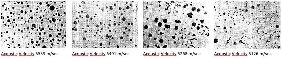
Ductile iron is an iron-carbon casting material whose matrix includes carbon in the form of nodular graphite particles. Rounded graphite nodules in the ductile iron matrix offer greater resistance to stress concentration when compared to graphite flakes (as in gray cast iron) and, therefore, inhibit the creation of cracks.
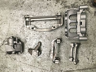
Safety-critical automotive components cast from ductile iron must be tested to verify that they include the correct percentage of nodularity. If a safety-critical casting experiences catastrophic failure, it can result in damage, injury, and, in the worst case, loss of life. Casting manufacturers routinely employ a destructive test method (microstructure analysis) to verify the correct nodularity of sample parts. Microstructure analysis is typically conducted in the metallurgical laboratory. At best, microstructure analysis is used only on a small sample of the total production.
A specific algorithm determines the velocity and the thickness of the iron part from the three time of flight values: TOF1, TOF2, and TOF3 (Figure 1). There is no need to know the thickness of the part to determine its velocity. As long as the part is in the correct position, it is automatically detected and measured. Data from this process can be sent to a PLC.
An easy-to-use user interface guides the operator step by step through the calibration process and enables automated measurement with clear results. The user interface is based on a GO/NOGO principle, enabling the results from a batch of parts to be closely monitored.
In addition to sound velocity measurement, it is also possible to use pulse-echo ultrasonic probes to verify certain casting features, such as the thickness of a wall or to detect laminar type defects.
Using ultrasonic velocity measurement, the nodularity of 100% of the manufactured parts can be inspected. By correlating the results of ultrasonic velocity measurement with results from destructively tested parts and adjusting the system using castings with known nodularity, production parts can be tested and the resulting velocity measurement compared with preset velocity limits to establish accept and reject limits. In addition to sound velocity measurement, it is also possible to use pulse-echo ultrasonic probes to verify certain casting features or to detect laminar defects.
The most common method for performing velocity measurement is to use precision test fixtures in an immersion tank. Ultrasonic probes are configured in pitchcatch (or through transmission) mode, and the time of flight (TOF) between the resulting ultrasonic echoes is measured and sound velocity and thickness are calculated. Sound velocity and thickness are measured at a location on the part where sound can be passed through two parallel surfaces that are normal to the probes.
Precisely fixing the parts relative to the ultrasonic probes is critical to the success of this application. Each tested part (including the reference standards that are used for setup) must be held in the same position relative to the probes. The geometry of all tested parts must be the same, and the reference standards must be produced from the same parts that will be tested.
While some customers still rely on manual loading and unloading of test parts, most high-volume production foundries utilize either mechanical pick-and-place devices or robots to load the parts into the test fixture and then unload the parts after the test result has been generated. Digital IO signals from the ultrasonic system enable accepted and rejected parts to be automatically sorted. In many cases, rejected parts are re-tested to ensure that the rejection was not due to positioning or some other variable in the inspection process.
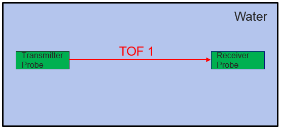
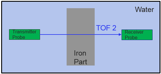
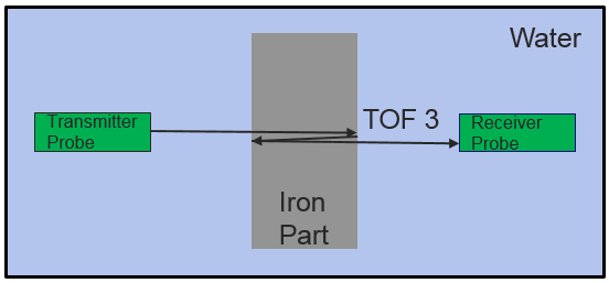
Figure 1. Three time of flight (TOF) measurements through an iron part being inspected.
A specific algorithm determines the velocity and the thickness of the iron part from the three time of flight values: TOF1, TOF2, and TOF3 (Figure 1). There is no need to know the thickness of the part to determine its velocity. As long as the part is in the correct position, it is automatically detected and measured. Data from this process can be sent to a PLC.
An easy-to-use user interface guides the operator step by step through the calibration process and enables automated measurement with clear results. The user interface is based on a GO/NOGO principle, enabling the results from a batch of parts to be closely monitored.
In addition to sound velocity measurement, it is also possible to use pulse-echo ultrasonic probes to verify certain casting features, such as the thickness of a wall or to detect laminar type defects.
Software interface
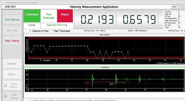
Figure 2. The system’s GO/NOGO user interface showing the velocity for the last batch of parts and an A-scan of the part under examination. The numerical values of velocity and thickness are clearly displayed along with a green and red alarm message for accepted or rejected parts.
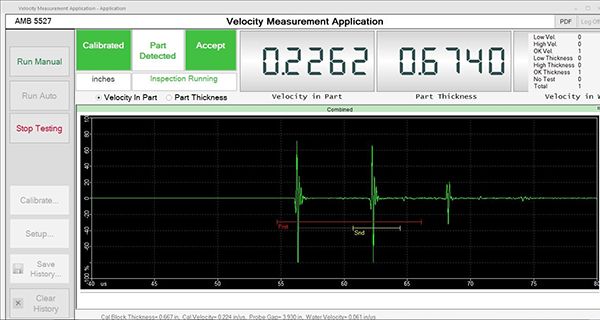
Figure 3. The same interface as Figure 2, but with a full-screen A-scan display of an accepted part.
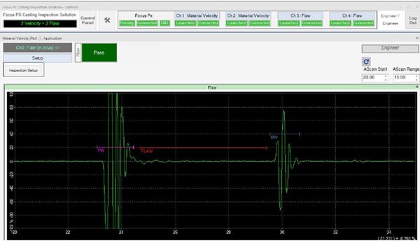
Figure 4. The user interface display being used to detect a fault between the front and back surfaces of a part. This configuration also displays a GO/NOGO alarm if an indication is encountered.
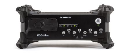
We offer two velocity packages, one with 2 channels and one with 4 channels; both include the FOCUS PX acquisition instrument, dedicated velocity software, and a digital I/O board:
- FPX-CUSTOM-Velocity 2ch-A (Q7750139)
- FPX-CUSTOM-Velocity 4ch-A (Q7750148)
On request, we can also offer an air-conditioned cabinet to integrate the solution into harsh environments.