Ultrasonic Testing of Carbon Steel Plates and Pipes - NDT
Overview
 Carbon Steel
Pipes and Plates
Olympus’ versatile solution for weld inspections uses a variety of techniques to achieve a productive and efficient inspection on plates and pipes from 4.5 in. OD and up. Phased array, time of flight diffraction, and conventional ultrasonic techniques can be used alone or in combination to achieve full-weld coverage with high probability of detection.
This solution also includes different scanning methods for accurate defect position and sizing. The stability and encoding capability offered by scanners results in better data quality as well as enables code compliant inspections. Scanning is done using different scanners for manual, manual-encoded, semiautomated or automated data collection method.
The Olympus carbon steel weld inspection solution brings together Olympus acquisition units, scanners, probes, and software tailored to your needs. The solutions allow length and depth sizing for code acceptance /rejection.
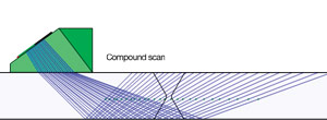
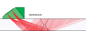
Compound Scan
|
Olympus’ updated NDT SetupBuilder software now offers the capability to perform compound scan beams. This innovative inspection strategy consists of a mix between sectorial and linear beams and offers many advantages such as:
|
Weld Series PA Probes and Wedges
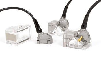 | The A31 and A32 phased array probes and wedges offer unique features for a new level of performance.
|
High Temperature Inspection
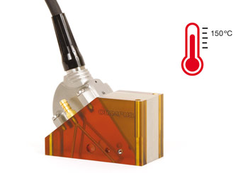 | A high-temperature wedge option compatible with the new A31 and A32 phased array probes and Olympus Mini-Wheel encoder is available upon request. The option enables the inspection of parts with a surface temperature up to 150 ⁰C. |
Passive-Axis Focusing (PAF) Wedges
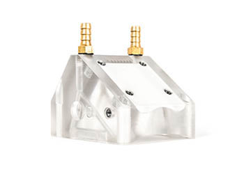 | Olympus’ patented passive-axis focusing wedge series helps compensate for beam divergence in the passive direction for pipe girth weld inspection. The smaller beam width enables the sizing of shorter flaws on the scan axis, helping lower rejection rates. Also, because the beam energy is focused, the signal-to-noise ratio (SNR) is improved, leading to sharper images of the defects. |
General Techniques
Ultrasonic Weld Inspection Solutions
The OmniScan flaw detector has an established track record for reliable and cost-effective phased array (PA) weld inspections as an alternative to radiography. Olympus ultrasonic weld inspection solutions provide an affordable means to inspect welds in compliance with major code and manufacturing requirements. An ideal combination of acquisition unit, scanner, encoder, and software, these solutions can be put to work virtually anywhere. Continuously improved and supported software makes the inspection of welds even easier, allowing you to complete your entire workflow more efficiently.
The Olympus weld inspection solutions applies to welds made of carbon steel or corrosion resistant alloy such as austenitic.
General Benefits:
- Fast weld inspection of different diameters, thickness, and materials
- 100% volumetric weld coverage
- Adaptable to butt welds, circumferential welds, long seams, one-sided access configuration, and most common weld profiles
- Portable for in-house and field inspections
Combining Different Techniques for Full Weld Coverage and Improved Efficiency
Phased Array Pulse-Echo Technique Phased array technique is based on the capacity to electronically modify ultrasonic beams generated by probes that contain multiple small elements. When these elements are excited using different time delays (focal laws), the beams are steered at different angles and focused at specific depths. | 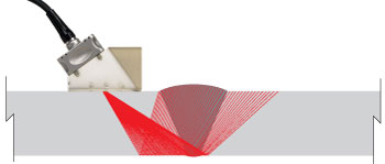 |
Conventional UT Pulse-Echo Technique This technique uses a single element transducer to generate an acoustic beam at a fixed angle. The echo coming back to the transducer is interpreted by the instrument to provide information on size and position. | 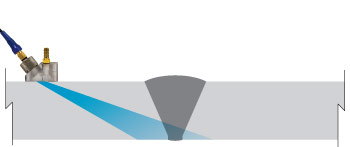 |
| Time-of-Flight Diffraction (TOFD) Technique Time-of-flight diffraction (TOFD) is an ultrasonic technique that relies on the property of defects such as cracks to diffract energy from their tips to the receiver probe when impinged by ultrasonic beams generated by the transmitter probe. TOFD technique uses a wide beam that provides good coverage and is independent of defect orientation. | 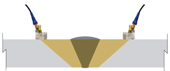 |
Transmit-Receive Longitudinal Wave (TRL) This technique uses separate transmit and receive probes to generate refracted longitudinal wave. The use of separate probes minimizes vulnerability to noisy material, which is especially beneficial for inspection of coarse grain alloy, such as austenitic and nickel. | 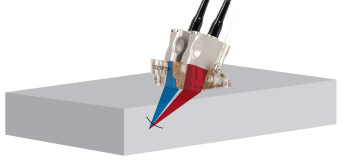 |
Surface Wave Technique The surface wave (creeping) technique is an ultrasonic test in which discontinuities are detected by the return of a creeping wave that tracks the surface of the component being tested. | 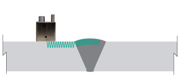 |
Ultrasonic Testing (AUT) in Lieu of Radiography Testing (RT)
Ultrasonic testing in lieu of radiography has proven very effective for pressure vessels, tanks, piping, and other weld configurations. Olympus ultrasonic weld inspection solutions features comply with ASME, API and other radiography replacement code requirements such as full raw data collection and the use of an encoder. Compared to conventional radiography, Olympus ultrasonic weld inspection solutions offer multiple benefits such as:
- No radiation safety hazards
- Eliminates work area disruption
- Real time digital archiving of inspection data
- Elimination of film archiving
- Improved productivity
- Improved probability of detection (POD)
Comparing the Indications
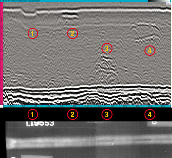 |
|
Measurement Capabilities
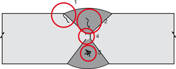
| ID | Type of Defect | Ultrasound (AUT) | Radiography (RT) |
| 1 | Toe crack |
• Position X, Y, and Z
• Length sizing • Height sizing |
• Position X and Y
• Length sizing |
| 2 | Centerline crack |
• Position X, Y, and Z
• Length sizing • Height sizing | • No detection |
| 3 | Porosity |
• Position X, Y, and Z
• Length sizing |
• Position X and Y
• Length sizing |
| 4 | Incomplete root penetration |
• Position X, Y, and Z
• Length sizing • Height sizing |
• Position X and Y
• Length sizing |
Benefits of the Olympus Ultrasonic Weld Inspection Solutions
| Olympus Ultrasonic Solutions | Radiography (RT) | |
| Absence of Radiation hazard | Yes | No |
| Absence of restricted area | Yes | No |
| Ease of deployment on site | Yes | No |
|
Probability of detection (POD)
(Planar defects such as crack and lack of fusion) | Very good | Poor |
| Inspection throughput | Very good | Good |
| Depth sizing capability | High accuracy | Poor |
| Length sizing capability | High accuracy |
Good accuracy
|
Scanning Methods
Scanning Methods
Our carbon steel weld solution can be used with different scanning options.
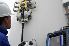
Automated
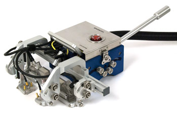
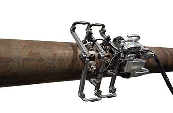
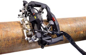
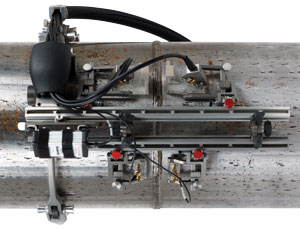
The WeldROVER scanner is the ideal automated scanning option for inspection of carbon steel weld using one pair of PA probes and up to three pairs of TOFD probes. It provides a faster and more stable movement of the probes for higher rate and more accurate data acquisitions. |
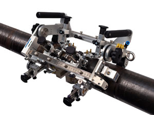
For efficient automated scanning of carbon steel welds in difficult-to-reach areas, the motorized SteerROVER scanner enables you to steer the scanner at a distance. Use the SteerROVER scanner with its rugged touch-screen handheld controller to perform reliable phased array (PA) ultrasonic testing of circumferential and longitudinal welds. The optional RECON camera kit assists in navigating the scanner, keeping the weld well centered, and helping ensure that the probes remain in contact with the surface. |
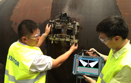
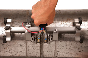
Manual and Manual Encoded
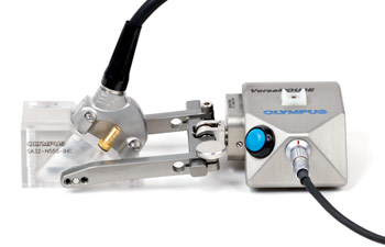
The weld can be scanned manually using one PA probe that can be encoded by attaching a Mini-Wheel encoder or by using a VersaMOUSE hand scanner. |
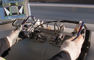
Semiautomated
|
| ||
|
| ||
|
TechniquesPhased array technique allows multiple beam angles, beam types and beam offset to be generated electronically. This allows greater flexibility for easy adaptation to different type of welds. Conventional UT technique can be an alternative to phased array when very high speed is required or when cost is preferred over flexibility. TOFD can be used alone for fast and simple inspection or as a complementary technique to pulse-echo. Combining phased array and TOFD techniques offers the best performance for most carbon steel weld inspection. Both techniques complete each other for excellent imaging, best POD, and flaw characterization. | Applications
|