Some of the parts that have required inspection lately include landing gears, which are subject to intense stress upon takeoffs and landings. The section that must be inspected is a cylinder possessing three different diameters in the zone of interest. The best way to inspect that zone is to use a phased-array technique with steering capabilities to simultaneously fire 40- to 70-degree shear wave refracted angles in the part.
Material Requirements
Inspection Method |
Ресурсы
Application Notes
Назад к ресурсам
Inspection of Landing Gear
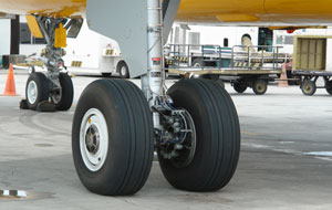 In today's aerospace market, the reliability of airplanes is more than ever a prime concern because airlines companies are trying to make their fleet last longer. To reach this goal safely, these companies must perform more inspections in order to ensure customer safety.
Продукты, используемые для этой цели
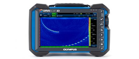
Дефектоскоп серии OmniScan™ X3 представляют собой полностью укомплектованное решение
УЗК ФР. Инновационный TFM и расширенные возможности фазированной решетки позволяют
с уверенностью выявлять любые дефекты, тогда как мощные программные средства и
простые рабочие процессы улучшают производительность.
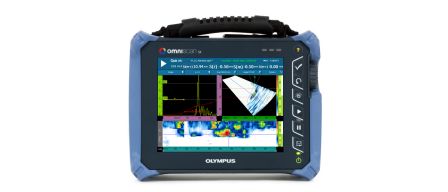
Одногруппный, легкий OmniScan SX оснащен 8.4-дюймовым (21,3 см) сенсорным экраном, легко читаемым в любой рабочей среде, и является простым и экономически выгодным решением. OmniScan SX доступен в двух конфигурациях: SX PA и SX UT. SX PA – это ФР-модуль 16:64PR, который, аналогично УЗ-модулю SX UT, оснащен традиционным каналом УЗ (UT) для контроля в режимах И-Э (импульс-эхо), РС (раздельно-совмещенный) или TOFD (дифракционно-временной метод контроля).
К сожалению, эта страница недоступна в вашей стране.
Let us know what you're looking for by filling out the form below.