This application note explains how to detect fastener hole cracks using adjustable sliding probes. The guidelines for adjustable sliding probes are similar to fixed sliding probes, so this application note includes some of the same instructions and details..
An Introduction to Sliding Probes
As the name implies, sliding probes move over fasteners in the inspection area in a sliding motion. Conventionally, these probes are used in spot probing (e.g., with a ring-encircling probe or moving a spot/surface probe around the periphery of a fastener).
Sliding probes are eddy current probes that operate in the reflection mode (transmit-receive). This means that the eddy currents are induced by the driver coil (transmitter) and detected by a separate pickup coil (receiver). With adjustable sliding probe types, a spacer is inserted between the two coil bodies.
Sliding probes are the fastest method to inspect large numbers of fastener holes for cracks. They can detect small defects in both the surface and subsurface layers. Adjustable sliding probes are particularly well suited to finding subsurface cracks in thick multilayer structures, such as wing skins. They differ with the fixed sliding probe types in that they are often moved at right angles to the crack direction (the probe is turned 90 degrees) in a 90-degree scan (see Appendix).
The sensitive area is located in the center of the probe between the coils. This area is directionally sensitive, so the engraved (normally green) detection line must be kept in the direction of the expected cracks. Two types of scans are possible: one scan centralized over the heads or two side (tangential) scans with one scan on each side of the fastener.
Surface and Subsurface Crack Detection
Adjustable sliding probes are normally used for subsurface crack detection. They are rarely used for surface cracks where the fixed sliding probes typically have the advantage. There are some exceptions, such as with large or magnetic fasteners and/or if the crack growth direction is at 90 degrees to the fastener row. The penetration will increase with larger probes, and depths of 0.75 in. (20 mm) are possible. However, small probes are the most common choice and can be used down to 100 Hz.
Liftoff AdjustmentWhen the probe is passed over the fastener head, an indication will be obtained similar to that of Figure 1. This is similar to fixed sliding probes. The liftoff is normally adjusted to be horizontal, as this is the conventional direction. The signal is not a straight line but a curve, so it is important to remember that we only need a reasonable compensation for the expected liftoff variations caused by paint and fastener head unevenness. A horizontal movement of the dot for the first 0.01 in. (0.25 mm) to 0.02 in. (0.5 mm) of liftoff is satisfactory. In Figure 1, it is the movement from the null point X to point Y, which will only cause a mainly horizontal shift of the display along that distance. Even this small distance can be a steep curve and may have to move slightly upwards before moving downwards (see Figure 2). The amount of vertical movement for the required liftoff is distributed so that the display only shifts slightly above or below the horizontal. | 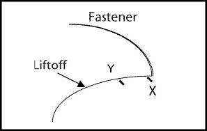 Fig. 1 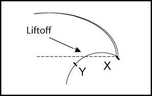 Fig. 2 |
Probe Adjustment
The spacer thickness between the coils is normally adjusted for the optimal detection. If the notch used for calibration is long enough (to give a good indication), it is quicker to centralize it over the head and perform one scan only (typical spacer thickness for the single scan inspection is approximately the fastener diameter). Check that the notch is still detectable if the probe is turned 180 degrees. This type of scan may not be possible with some large head or magnetic fasteners.
For tangential scans, a thinner spacer is often better. However, the final decision depends on the experimental results obtained with the reference standard and the structure to be inspected. The spacer thickness range can vary from 0 (no spacer) for inspections close to the surface and small fastener heads to a maximum of about 0.3 in. (8 mm) for deep penetration on large heads with bigger probes. A wider spacer will give more tolerance to probe deviation as the sensitive area becomes wider, but the instrument will require more gain.
Signal InterpretationWhen the probe moves over a fastener hole with no cracks in the normal 90-degree scan, the indication is narrow, but if we scan at 0 degrees, the indication becomes a loop (see Figure 3 and Appendix: Scan Directions to Help Ensure All Cracks Are Evaluated). The loop is produced by a continuous phase change as the driver and pickup coils travel over the fastener and is wider than with the fixed probes. When the dot is at point A, the probe is totally centralized (common to both scanning directions). | 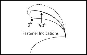 Fig. 3 |
Crack DetectionWhen the probe moves over a fastener hole with a crack, the indication changes and typically will create a larger loop and vertical movement (see Figure 4). The main difference between scanning in the crack direction or at right angle to the crack is the shape of the indication. The dotted line shows the indication obtained when the probe travels over the length of the crack (0° scan). The solid line shows the indication from traveling at right angles to the crack (the normal 90° scan). When the crack is scanned slowly along its length, the phase changes, displaying a loop. But when moving at right angles to the crack, it is seen by the probe abruptly, and gives a sharp narrow signal. This signal will meet the loop at some point in its travel depending on the probe alignment. Both these signals can be observed by scanning the same fastener hole in the two directions (see Appendix: Scan Directions to Help Ensure All Cracks Are Evaluated). If two cracks on opposite sides of the fastener hole are present with the probe moving at right angles and centralized over the fastener, the indications will typically add up to a larger indication. This is because both are being detected at the same time (with a fixed probe they would normally be detected one after the other in a 0° scan). | 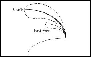 Fig. 4 |
Variables: Probe Scan DeviationIt is important to try to keep the probe centralized over the fastener heads. This corresponds to a maximum indication for the fastener and the crack. In Figure 5, the indication A corresponds to a perfectly centralized probe, while indications B and C correspond to increasing deviation from the center line. The dotted line marks the path of the changing deviation (see Appendix). If the probe deviates from the center line, the crack indication will move along the loop that we saw in Figure 4 and is now presented in Figure 5. The crack indication is at A when the probe is centralized. It moves toward B as it deviates in one direction or C as it deviates in the opposite direction. Point B gives an improved indication even if it loses a small amount of amplitude it gained in phase, leading to a better separation angle (this is because we deviated to the side where the crack is located). For this reason, two tangential side scans are more sensitive to smaller cracks than one centralized scan. When the probe deviates in the opposite direction, the signal from the crack moves toward point C, where it loses too much phase and amplitude and starts looking more like the normal fastener indication (particularly for a small defect, as represented in Figure 5). Therefore, a second tangential scan in the opposite side is needed. |  Fig. 5 |
Variables: Crack Angle DeviationA reduction in the crack indication occurs when the crack is at an angle to the probe scan direction. This happens if the crack is not completely at 90 degrees to the normal probe scan or changes direction as it grows. The effect is also very similar if the probe is not at right angles but at a smaller angle of attack (see Appendix: Scan with a Deviation Angle). The adjustable sliding probes can detect cracks up to about 30 degrees off angle and will give a reduced indication proportional to the amount of deviation (see Figure 6). The effect is similar to that obtained with the fixed sliding probes. | 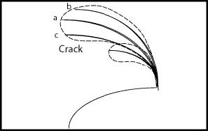 Fig. 6 |
Variables: Electrical Contact
When inspecting fasteners that have just been installed or reference standards that have close contact with the aluminum skin plate, it is not unusual to obtain a smaller than normal indication. In some extreme cases, the fastener indication may disappear almost completely. This is due to the good electrical contact between the fastener and the skin that allows the eddy currents to circulate without finding the boundary; therefore, they have no obstacle or barrier. Figure 7 shows the decrease of the fastener indication due to close contact.
This problem is found more frequently with riveting and rarely with other fasteners, particularly if used with nuts or collars. However, due to this effect, it is recommended to paint the holes on the reference standard before fastener installation. In this way, the reference standard will simulate the real-life structure from temperature changes, moisture, and movement that creates a natural oxide layer between fastener and skin.
Other Best Practices for Crack Detection:
- Cracks are considered detectable up to +/- 30 degrees; however, this also depends on depth and crack length. Longer cracks are more likely to be detected off angle.
- It is important to avoid the probe hitting the edge of the fastener head. If the spacer does not provide a large enough gap to provide clearance over the fastener heads, then it is advisable to create one using thin strips (skis) of tape.
- To provide the best presentation, it is common practice to set the vertical gain a few dB above the horizontal gain.
- It is often helpful to use a nonmetallic straight edge to guide the probe over the line of fasteners, particularly if heavy paint makes it difficult to see the heads. In extreme cases, it may be necessary to locate two fasteners to locate the row using the sliding probe.
- If the fastener heads are not reasonably aligned, it is probably better to scan by hand, taking care to guide the probe along with the same alignment to the fastener head.
- To find a crack direction more accurately, approach the fastener at different angles until you obtain the largest indication.
- When inspecting magnetic steel fasteners, it is often helpful to place a very thin magnetic steel shim under the driver coil. As the probe will see the steel shim at all times, the dot will move less when traveling from the aluminum to the magnetic fastener head. As a result, it will produce a smaller indication.
- If the fastener spacing is close enough to fit a head under each coil, a downwards indication will be obtained. This indication is normally easily identified from a crack.
Appendix
Typical Center Scan with an Adjustable Probe 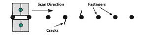 | Scan Directions to Help Ensure All Cracks Are Evaluated 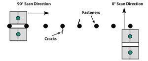 |
Scan with a Deviation Angle 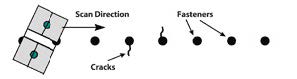 | Typical Side Scan (Tangential) with an Adjustable Probe (Two Scans Normally Required) 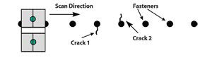 |