An Introduction to Ultrasonic Thickness Gauging
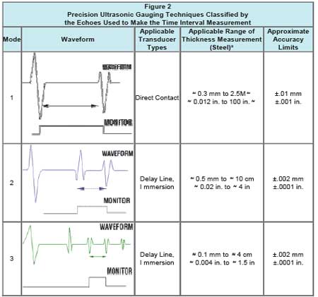
by Tom Nelligan Ultrasonic thickness gauging is a widely used nondestructive test technique for measuring the thickness of a material from one side. It is fast, reliable, and versatile, and unlike a micrometer or caliper it requires access to only one side of the test piece. The first commercial ultrasonic gauges, using principles derived from sonar, were introduced in the late 1940s. Small, portable instruments optimized for a wide variety of test applications became common in the 1970s. Later advances in microprocessor technology led to new levels of performance in today's sophisticated, easy-to-use miniature instruments. Virtually any common engineering material can be measured ultrasonically. Ultrasonic thickness gauges can be set up for metals, plastics, composites, fiberglass, ceramics, and glass. On-line or in-process measurement of extruded plastics and rolled metal is often possible, as is measurement of individual layers or coatings in multilayer fabrications. Liquid levels and biological samples can also be measured. Ultrasonic gauging is always completely nondestructive, with no cutting or sectioning required. Sound energy can be generated over a broad frequency spectrum. Audible sound occurs in a relatively low frequency range with an upper limit around twenty thousand cycles per second (20 Kilohertz). The higher the frequency, the higher the pitch we perceive. Ultrasound is sound energy at higher frequencies, beyond the limit of human hearing. Most ultrasonic testing is performed in the frequency range between 500 KHz and 20 MHz, although some specialized instruments go down to 50 KHz or lower and as high as 100 MHz. Whatever the frequency, sound energy consists of a pattern of organized mechanical vibrations traveling through a medium such as air or steel according to the basic laws of wave physics. Ultrasonic thickness gauges work by very precisely measuring how long it takes for a sound pulse that has been generated by a small probe called an ultrasonic transducer to travel through a test piece and reflect back from the inside surface or far wall. Because sound waves reflect from boundaries between dissimilar materials, this measurement is normally made from one side in a "pulse/echo" mode. The transducer contains a piezoelectric element which is excited by a short electrical impulse to generate a burst of ultrasonic waves. The sound waves are coupled into the test material and travels through it until they encounter a back wall or other boundary. The reflections then travel back to the transducer, which converts the sound energy back into electrical energy. In essence, the gauge listens for the echo from the opposite side. Typically this time interval is only a few millionths of a second. The gauge is programmed with the speed of sound in the test material, from which it can then calculate thickness using the simple mathematical relationship T = (V) x (t/2) Sound waves in the megahertz range do not travel efficiently through air, so a drop of coupling liquid is used between the transducer and the test piece in order to achieve good sound transmission. Common couplants are glycerin, propylene glycol, water, oil, and gel. Only a small amount is needed, just enough to fill the extremely thin air gap that would otherwise exist between the transducer and the target. 3. Measurement modes There are three common ways of measuring the time interval that represents the sound wave's travel through the test piece. Mode 1 is the most common approach, simply measuring the time interval between the excitation pulse that generates the sound wave and the first returning echo and subtracting a small zero offset value that compensates for fixed instrument, cable, and transducer delays. Mode 2 involves measuring the time interval between an echo returned from the surface of the test piece and the first backwall echo. Mode 3 involves measuring the time interval between two successive backwall echoes. The type of transducer and specific application requirements will usually dictate the choice of mode. Mode 1, used with contact transducers, is a general purpose test modeand is recommended for most applications. Mode 2, used with delay line or immersion transducers, is most often used for measurements on sharp concave or convex radiuses or in confined spaces with delay line or immersion transducers, for on-line measurement of moving material with immersion transducers, and for high-temperature measurements with high-temperature delay line transducers. Mode 3, also used with delay line or immersion transducers, typically offers the highest measurement accuracy and the best minimum thickness resolution in a given application,at the expense of penetration It is commonly used when accuracy and/or resolution requirements cannotbe met in Mode 1 or 2. However Mode 3 can be used only on materials that produce clean multiple backwall echoes, typically low attenuation materials like fine grain metals, glass, and most ceramics.
Commercial ultrasonic thickness gauges are generally divided into two types: corrosion gauges and precision gauges. The single most important application for ultrasonic gauging is measuring the remaining wall thickness of metal pipes, tanks, structural parts, and pressure vessels that are subject to internal corrosion that can't be seen from the outside. Corrosion gauges are designed for this type of measurement, using signal processing techniques that are optimized for detecting the minimum remaining thickness in a rough, corroded test piece, and they use specialized dual element transducers for this purpose. Precision gauges that use single element transducers are recommended for all other applications, including smooth metals as well as plastics, fiberglass, composites, rubber, and ceramics. With a wide variety of transducers available, precision gauges are extremely versatile and in many cases can measure to an accuracy of +/- 0.001" (0.025 mm) or greater, higher than the accuracy that can be achieved with corrosion gauges. 5. Transducer types Contact transducers: As the name implies, contact transducers are used in direct contact with the test piece. Measurements with contact transducers are often the simplest to implement and they are usually the first choice for most common thickness gauging applications other than corrosion gauging. In any ultrasonic gauging application, the choice of gauge and transducer will depend on the material to be measured, thickness range, geometry, temperature, accuracy requirements, and any special conditions that may be present. Olympus NDT can provide full details for specific applications. Listed below are the major factors that should be considered. A more detailed discussion of the principles of ultrasonic gauging can be found in our Thickness Gauge Tutorial on this web site. Also see individual application notes for discussions of particular test procedures. |