An Introduction to Ultrasonic Transducers for Nondestructive Testing
By Tom Nelligan
The high-frequency sound waves used for flaw detection and thickness gaging in ultrasonic nondestructive testing applications are generated and received by small probes called ultrasonic transducers. Transducers are the starting point for any ultrasonic test setup, and they come in a wide variety of frequencies, sizes, and case styles to meet inspection needs ranging from flaw detection in enormous multi-ton steel forgings to thickness measurement of paper-thin coatings. | 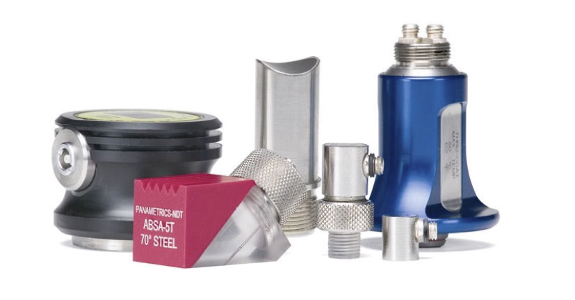 |
A transducer is generally defined as any device that converts one form of energy into another. The subject of this paper is the ultrasonic transducers used for thickness gaging and conventional flaw detection. Phased array probes that utilize multiple elements to generate steered sound beams are described in detail in our Inside a Phased Array Transducer tutorial.
In ultrasonic NDT, transducers convert a pulse of electrical energy from the test instrument into mechanical energy in the form of sound waves that travel through the test piece. Sound waves reflecting from the test piece are, in turn, converted by the transducer into a pulse of electrical energy that can be processed and displayed by the test instrument. In effect, the transducer acts as an ultrasonic speaker and microphone, generating and receiving pulses of sound waves at frequencies much higher than the range of human hearing.
Typically, the active element of an NDT transducer is a thin disk, square, or rectangle of piezoelectric ceramic or composite that converts electrical energy into mechanical energy, and vice versa. This element is sometimes informally called the crystal because, in the early days of ultrasonic NDT, elements were made from quartz crystals; however, ceramics such as lead metaniobate and lead zirconium titanate have long been used in most transducers. Recent years have seen increasing use of composite elements in which the traditional solid ceramic disk or plate is replaced by a micro-machined element in which tiny cylinders of piezoelectric ceramic are embedded in an epoxy matrix. Composite elements can provide increased bandwidth and improved sensitivity in many flaw detection applications.
| Figure 1. Typical single element and dual element transducer construction. |
When it is excited by an electrical pulse, this piezoelectric element generates sound waves, and when it is vibrated by returning echoesit generates a voltage. The active element is protected from damage by a wearplate or acoustic lens and backed by a block of damping material that quiets the transducer after the sound pulse has been generated. This ultrasonic subassembly is mounted in a case with appropriate electrical connections. All common contact, angle beam, delay line, and immersion transducers utilize this basic design. The phased array probes used in imaging applications simply combine a number of individual transducer elements in a single assembly. Dual element transducers, commonly used in corrosion survey applications, differ in that they have separate transmitting and receiving elements separated by a sound barrier, no backing, and an integral delay line to steer and couple the sound energy rather than a wearplate or lens. Figure 1 illustrates typical transducer construction.
While the basic concept is simple, transducers are precision devices that require great care in design, material selection, and manufacturing to help ensure optimum and consistent performance. The transducers commonly used in conventional ultrasonic NDT fall into five general categories based on their design and intended use.
Contact transducersAs the name implies, contact transducers are used in direct contact with the test piece. A thin, hard wearplate cut to a thickness of one-quarter the wavelength protects the active element from damage in normal use. Contact transducers (Figure 2) are commonly used in flaw detection applications involving straight beam tests, such as when looking for voids in metal ingots or delaminations in composites, and also in many thickness gaging applications. |
Figure 2. A typical contact transducer. |
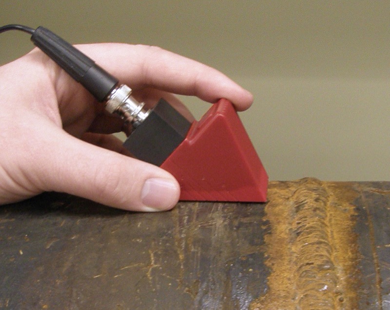
Angle beam transducersThese are similar in construction to contact transducers, but are designed to be used with angle beam wedges to generate sound tilted at an angle to the coupling surface. Wedges are commonly configured to generate refracted shear waves at 45, 60, or 70 degrees. They are standard in most weld inspections since testing the most common weld geometries requires aiming sound waves at an angle. These transducers are referenced in all common weld inspection codes. |
Figure 3. A typical angle beam transducer with wedge. |
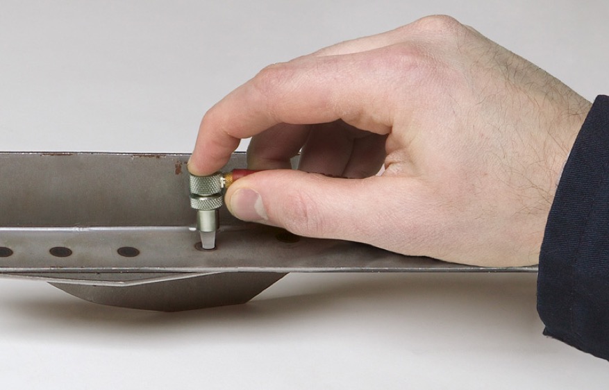
Delay line transducersDelay line transducers incorporate a cylinder of plastic, epoxy, or fused silica known as a delay line between the active element and the test piece. A major reason for using them is for thin material applications like testing spot welds in sheet metal or measuring very thin test pieces, where it is important to separate the excitation pulse recovery from backwall echoes. A delay line is often used as a thermal insulator, protecting the heat-sensitive transducer element from direct contact with hot test pieces. Delay lines can also be shaped or contoured to improve sound coupling in sharply curved or confined spaces. |
Figure 4. A delay line transducer. |
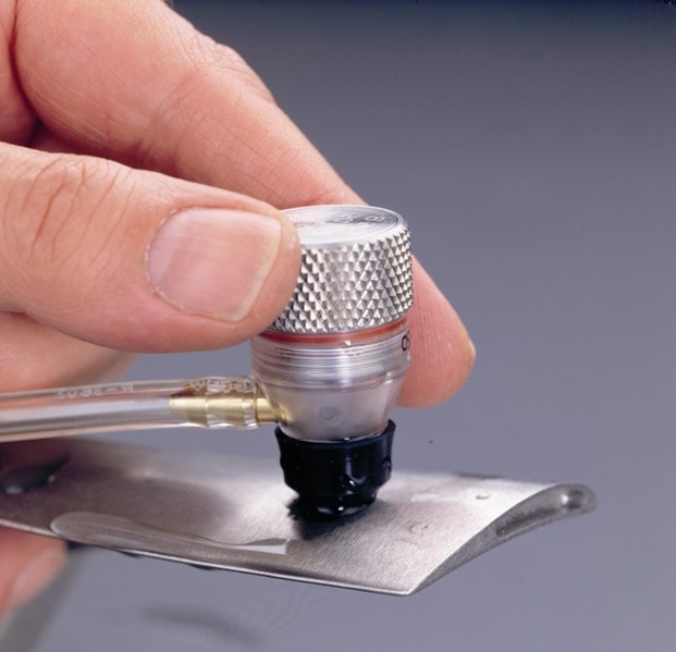
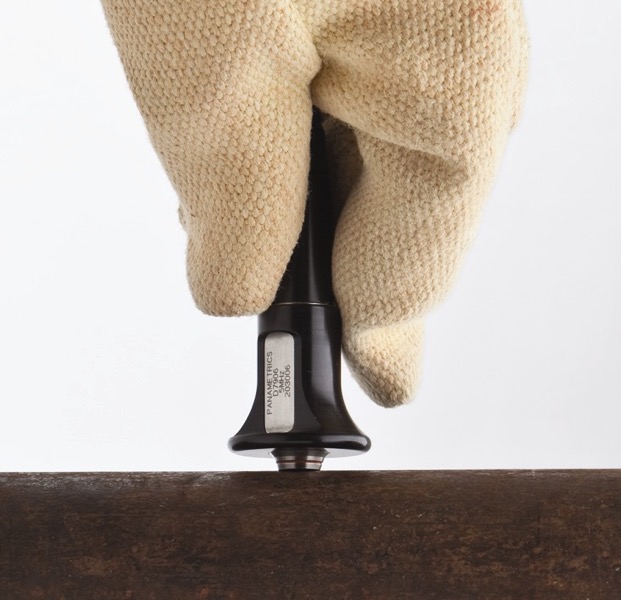
Immersion transducersImmersion transducers, as the name implies, are designed to be immersed in water and use a column or bath of water to couple sound energy into the test piece. These transducers frequently incorporate an acoustic lens that focuses the sound beam into a small spot, increasing sensitivity to small reflectors. They are commonly used for on-line or in-process tests on moving parts, for scanned tests, and for optimizing sound coupling into sharp radiuses, grooves, or channels in test pieces with complex geometry. |
Figure 5: A typical immersion transducer with handheld bubbler. |
Dual element transducersDual element transducers, or simply "duals," are used primarily for tests involving rough, corroded surfaces. They incorporate separate transmitting and receiving elements mounted on a delay line at a small angle to focus sound energy a selected distance beneath the surface of a test piece. Although thickness measurement with duals is sometimes not as accurate as with other types of transducers, they usually provide significantly better performance in corrosion survey applications due to their higher sensitivity to pitting and improved near surface resolution. They are also commonly used for high-temperature testing since most duals will tolerate contact with hot surfaces, and for flaw detection in rough-surfaced castings. |
Figure 6. An example of al dual element transducer. |
The high-frequency vibrations that are the basis of ultrasonic NDT commonly occur as either longitudinal waves (particle motion parallel to wave direction) or shear waves (particle motion perpendicular to wave direction). All commonly used NDT transducers generate longitudinal waves. Thickness gaging and straight beam flaw detection normally use longitudinal waves, which are the easiest to create and propagate well through typical engineering materials. Shear waves are used in most angle beam inspections of welds and similar structures. Angle beam assemblies use refractive mode conversion to turn the longitudinal waves generated by the transducer into shear waves, which have a shorter wavelength than comparable longitudinal waves and are thus more sensitive to small reflectors. Some immersion tests also utilize shear waves generated by mode conversion. Other modes, such as surface waves and plate waves, also exist as well as contact transducers that generate shear waves directly, but these are employed only in specialized tests.
In addition to the various design types, ultrasonic transducers are available in a wide variety of frequencies, sizes, and bandwidths to meet different application needs. Most ultrasonic testing is performed at frequencies between 1 MHz and 10 MHz, however commercially available transducers range in frequency from less than 50 KHz to greater than 200 MHz. (By comparison, the range of human hearing is from approximately 20 Hz to 20 KHz, decreasing as a person gets older.) Commonly used element sizes range from as small as 0.125 in. (3 mm) to 1.5 in. (38 mm). Bandwidth, or the span of frequencies contained in the spectrum generated by the transducer, may be either narrow or broad.
Why all these choices? Because of basic wave physics, each of these parameters affects the behavior of the sound wave in ways that will have advantages and disadvantages in a given test.
- Higher frequencies permit detection of smaller flaws and measurement of thinner test pieces, but the sound energy won’t travel as far as at lower frequencies. Lower frequencies provide better penetration of thick test pieces, especially in materials like cast metals and plastics that transmit sound less efficiently, but they will be less sensitive to small flaws and may not measure thin sections.
- Large elements can permit quicker scanning of a test piece, but will reduce sensitivity to small reflectors and may not couple well onto curved surfaces like pipes. Smaller elements will be more sensitive to small reflectors and will couple better onto curved surfaces, but will not test large areas as quickly.
- Broadband transducers have good near surface resolution, enabling detection of flaws close to the surface and measuring thin parts. Narrowband transducers have better penetration and can generate stronger echoes from reflectors, but exhibit less axial resolution.
So which one is best for your application? In many cases, the choice of a transducer will be dictated by an established inspection code or test procedure that calls out a specific type. But if no procedure is available, the inspector must decide on the best transducer for the test based on his or her knowledge of ultrasonic theory, the defined test goals (such as the type and size of flaws that need to be resolved), and the specific material, thickness, and geometry of the test piece. While knowledge of theory and some NDT experience are essential, in some cases an inspector’s skills must be supplemented by experimentation on test samples to determine what transducer will work best.
Transducers are commonly supplied with test forms (Figure 7) that document basic performance characteristics, typically with respect to a generally recognized test procedure such as ASTM E-1065. These forms verify product consistency and adherence to specifications. In the example below, the test form documents peak and center frequencies, upper and lower frequency limits, bandwidth, and RF waveform under the listed test conditions. For advanced users, manufacturers can also supply more specialized documentation such as electrical impedance plots and beam profiles when required.
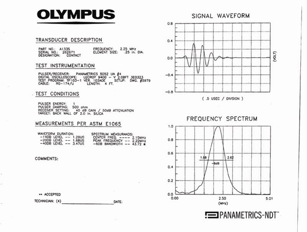 |
| Figure 7. An example of a manufacturer’s transducer test form. |
While the transducer is an essential part of any test, instrument setup is also a critical factor. Instrument manufacturers will typically supply recommended procedures for calibrating their instrument with a given transducer for a given test. At a minimum, this involves setting gain (sensitivity) levels and zero offset with respect to the transducer being used and material sound velocity. This is usually accomplished with the aid of appropriate test blocks or reference samples. Depending on the instrument and the test, other parameters such as pulse energy, damping, and receiver filtering may also need adjustment. A properly trained inspector will be familiar with all of these settings and know how to use them to optimize test results in each case. Good practice also dictates that instrument settings be verified whenever the transducer is changed, or if the transducer shows signs of excessive wear. Many test procedures require periodic calibration checks during inspections to help ensure that nothing affecting test results has changed.
Transducers from quality manufacturers will usually last for years if treated well, however, they are sensitive devices that should be protected from damage due to excessive shock or vibration, abrasion from scraping against rough surfaces, exposure to corrosive liquids, and overheating. Unless specified for high-temperature use, most single element transducers should not be subjected to temperatures higher than approximately 125 °F (50 °C). Transducers with significant visible surface wear should be checked for performance before use. Dual element transducers can frequently be resurfaced, and delay lines can be easily replaced, but damage to contact transducers is non-repairable.
High-pressure environments, underwater use, and other special environments should be reviewed with the transducer manufacturer. In cases where test piece geometry restricts access, special transducers can sometimes be designed to fit. Again, consultation with the manufacturer is recommended.
Olympus can provide more specific information regarding the range of products available as well as technical support in the area of transducer selection. Consult your Olympus representative for further details.
For further reading:
Ultrasonic Transducers Technical Notes