Introduction to Hall Effect Thickness Gaging with the Magna-Mike 8600
by Tom Nelligan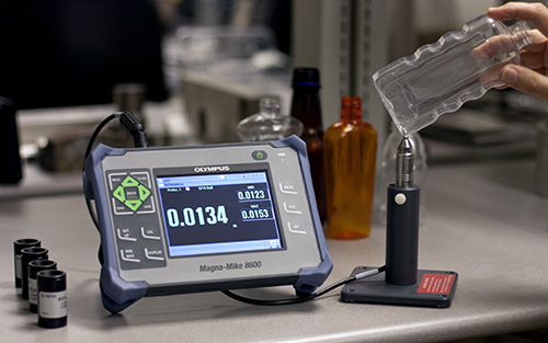
Hall Effect thickness gages like the Olympus Magna-Mike 8600 are small, lightweight instruments designed to make fast, accurate, and repeatable measurements of non-magnetic materials such as plastics, glass, composites, aluminum, and titanium. The first commercial instruments of this type were introduced in the 1980s and they are now widely used in a number of industries. Wall thickness is measured by placing a small steel target (ball, disk, or wire) on one side of the test piece and the
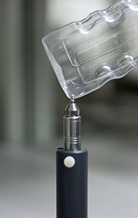
magnetic probe on the opposite side. The Magna-Mike precisely measures the distance between the probe tip and the target, which corresponds to the thickness of the wall.
1. What can be measured
Hall Effect gages can potentially measure any non-magnetic material whose geometry permits placing a probe tip on one side of a wall and a small target like a steel ball on the other, up to a maximum thickness of approximately 1 inch or 25 mm. Materials that can be measured include all types of plastics and composites, aluminum, titanium, and other nonferrous metals, glass, wood and paper products, and certain nonmagnetic stainless steel alloys. Measurement accuracy can be as close as +/- 1% of wall thickness and is typically +/- 3% or better. Important measurement applications include:
- Plastic bottles and packaging
- Molded plastic parts like containers and tanks
- Air bag tear seams
- Small diameter plastic and nonmagnetic metal tubing
- Glass containers and scientific glassware
- Aluminum beverage cans
- Paper and foam food containers
- Machined metal parts (except magnetic steel and iron)
- Plywood and particle board
- Aerospace parts including turbine blades
2. How Hall Effect gages work
 A Hall Effect sensor is a specialized electronic semiconductor which responds to changes in a magnetic field by varying a voltage that appears across its surface as a current passes through it. A detailed explanation of the physics behind the Hall Effect can be found here: en.wikipedia.org/wiki/Hall_Effect. When a Hall Effect sensor is used for thickness gaging, it is incorporated in a small probe along with a strong magnet that creates a magnetic field around the sensor. A target such as a small steel ball bends the magnetic field generated by the probe magnet, with the bending effect increasing as the target comes closer. As the test piece thickness and thus the
distance between the target and the probe changes, the voltage across the Hall Effect sensor also varies in a predictable way. Once the instrument has been calibrated for a particular probe and target, these voltage changes can be converted to thickness readings through a software algorithm that utilizes an established calibration curve.
A Hall Effect sensor is a specialized electronic semiconductor which responds to changes in a magnetic field by varying a voltage that appears across its surface as a current passes through it. A detailed explanation of the physics behind the Hall Effect can be found here: en.wikipedia.org/wiki/Hall_Effect. When a Hall Effect sensor is used for thickness gaging, it is incorporated in a small probe along with a strong magnet that creates a magnetic field around the sensor. A target such as a small steel ball bends the magnetic field generated by the probe magnet, with the bending effect increasing as the target comes closer. As the test piece thickness and thus the
distance between the target and the probe changes, the voltage across the Hall Effect sensor also varies in a predictable way. Once the instrument has been calibrated for a particular probe and target, these voltage changes can be converted to thickness readings through a software algorithm that utilizes an established calibration curve.
It is important to remember that what Hall Effect gages actually measure is the distance between the probe tip and the target, and thus they measure wall thickness indirectly. For accurate thickness measurements, the operator must insure that the probe and the target are properly aligned with each other and positioned in close contact with the test piece. This is discussed further in Section 4.
3. Probes and targets
The Olympus Magna-Mike 8600 is available with two types of probes, two type of wear cap tips, and four types of targets to accommodate a range of thicknesses as well as a wide variety of test piece geometries.
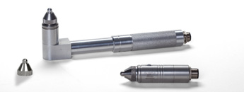
(a) Probe Type - Straight and right angle probes are available. The straight probe, held vertically in a probe stand, is most commonly used for benchtop inspections. The right angle probe is designed for use in situations where part geometry limits access, as in some tests involving nonferrous castings.
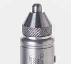 Standard Wear Cap | 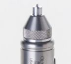 Removable Chisel Tip Cap |
(b) Wear caps - The replaceable probe wear cap fits over the active Hall sensor and makes contact with the test piece. Wear caps are available with a standard rounded tip or with a chisel point for applications in which the probe must fit into a narrow channel or groove. They are interchangeable and can be used with all standard targets.
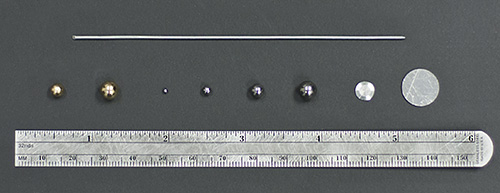
(c) Targets - The available targets types are standard steel balls, magnetic balls, disks, and wires. All but the wires are available in multiple sizes. Standard steel balls are available in diameters of 1/16th inch (1.58 mm), 1/8th inch (3.17 mm), 3/16th inch (4.76 mm), and ¼ inch (6.35 mm). These are the default targets for most applications where material thickness does not exceed 0.4 inch or 10 mm. Magnetic balls are available in diameters of 3/16th inch (4.76 mm) and ¼ inch (6.35 mm). These are used for measurements in the range between 0.4 inch (10 mm) and 1 inch (25 mm) and also in cases where the increased magnetic attraction between the probe and target makes target positioning easier. Disk targets are used when measurements must be made in narrow channels or grooves. These are available in 0.5 inch (12.7 mm) diameter with a flat edge, and 0.250 inch (6.35 mm) diameter with a v-edge for very narrow grooves. Finally, 0.045 inch (1.14 mm) diameter wire is available for applications in which the target must be inserted deep into a hole or similar geometrically limited access point.
4. Typical range and accuracy
The chart below shows typical range and accuracy for standard targets. Larger targets can typically offer a greater measurement range as well as best accuracy on thinner measurements. The following factors should be considered when choosing a target:
- Minimum curvature of the material
- Maximum thickness measurement
- Accuracy needed for measurement
- Compressibility of the material (larger or magnetic balls will compress the material more then smaller or none magnetic target balls)
- Surface hardness: Magnetic target balls will slide along the surface unlike the non-magnetic target balls that roll. The user should uses caution when using magnetic balls to ensure that the surface of the material will not be scratched by a magnetic target ball.
In general, the best results will be obtained by using the largest target ball that moves freely in the test piece.
| Targets | Min Thickness | Max Thickness | Accuracy with Standard Wear Cap | |
| Basic Calibration | Multipoint | |||
| 1/16 in. (1.58 mm) ball (80TB1) | 0.0001 in. (0.001 mm) | 0.090 in. (2.3 mm) | 4% | 3% |
| 1/8 in. (3.17 mm) ball (80TB2) | 0.0001 in. (0.001 mm) | 0.300 in. (7.6 mm) | 4% | 2% |
| 3/16 in. (4.76 mm) ball (80TB3) | 0.0001 in. (0.001 mm) | 0.360 in. (9.1 mm) | 3% | 1% |
| 1/4 in. (6.35 mm) ball (80TB4) | 0.0001 in. (0.001 mm) | 0.500 in. (12.7 mm) | 3% | 1% |
| New 3/16 in. (4.76 mm) magnetic ball (86TBM3) | 0.160 in. (4.06 mm) | 0.750 in. (19.05 mm) | 3% | 1% |
| New 1/4 in. (6.35 mm) magnetic ball (86TBM4) | 0.160 in. (4.06 mm) | 1.00 in. (25.4 mm) | 3% | 1% |
| 0.500 in. (12.7 mm) flat disk (80TD1) | 0.0001 in. (0.001 mm) | 0.360 in. (9.1 mm) | 3% | 2% |
| 0.250 in. (6.35 mm) V-edge disk (80TD2) | 0.0001 in. (0.001 mm) | 0.240 in. (6.0 mm) | 3% | 2% |
| New 0.045 in. (1.14 mm) dia. wire (86TW1) | 0.160 in. (4.06 mm) | 0.500 in. (12.7 mm) | 3% | 2% |
| Note: | Measurement tolerance = +/- [(accuracy x thickness) +0.0001 in.] Measurement tolerance = +/- [(accuracy x thickness) +0.003 mm] |
5. Additional factors to consider
Calibration: Hall Effect instruments must be calibrated before use, using the same probe and target that will be employed for measurements. This is done by taking readings with no target, with the target touching the probe (zero thickness), and at two or more reference thicknesses. This permits the instrument to generate a calibration table that plots voltage changes versus thickness. The calibration matches each target being used to an internal lookup table from the unit's memory. The calibration also measures the two extremes of the target's possible locations (Ball On and Ball Off) and assigns these endpoints to the lookup table. Additional calibration points at known thicknesses are used to fine-tune the table for best accuracy. During operation, calibration should be verified whenever probe orientation or environmental temperature changes.
 Free movement of target balls: Because Hall Effect gages measure the distance between the probe tip and the target, geometrical obstruction of the ball will cause inaccurate measurements. Similar, the probe tip must be in close contact with the part. The chisel point wear cap should be
used when surface geometry limits the contact area.
Free movement of target balls: Because Hall Effect gages measure the distance between the probe tip and the target, geometrical obstruction of the ball will cause inaccurate measurements. Similar, the probe tip must be in close contact with the part. The chisel point wear cap should be
used when surface geometry limits the contact area.
Nearby Magnetic Objects and Magnetic Fields: The probe should never be used on or near ferromagnetic materials such as carbon steel benches, shelves, brackets, supports, watches or jewelry, or near electric motors or similar sources of electromagnetic interference. It should be kept at least 8 in. (200 mm) from computers. All of these things can influence the probe's magnetic field and cause inaccurate measurements. This is especially important when measuring near the maximum specified thickness for each target type.
Probe orientation: Because the Magna-Mike 8600 measures thickness by monitoring small changes in a magnetic field, its calibration process includes an automatic compensation for the effects of the earth's magnetic field. Most commonly, the probe is held at a constant orientation, vertically in a stand. However in cases where the probe is used at a different orientation (such as being held horizontally), or when the orientation is changing as in scanning the outside of a curved part, calibration must be updated. In the Magna-Mike 8600, the Q-Cal function is used to make this correction. This is especially important when measuring near the maximum specified thickness for each target type. Simply remove the target and press the Q-Cal key while the probe is held at the desired orientation.
Rough or vertical test surfaces: Surface roughness or grooves can cause target balls to momentarily hang up as the probe is scanned, increasing the apparent thickness. When measuring vertical surfaces with the probe in a horizontal orientation, gravity can cause the target ball to fall away from the centerline of the probe. In these cases the MIN Capture mode should be used to insure measurement of true minimum thickness.
Wire targets: When using the wire target, the probe tip must be positioned at least 1 in. (25 mm) from the end of the wire. The wire must be pressed securely against the test piece at the point of measurement, since as with any other target the Magna-Mike is actually measuring the distance to the target, not the wall thickness directly. The angular alignment between the probe tip and the wire (typically perpendicular) must be maintained, since wire tilt can affect readings. The wire target should not be kinked or bent.
6. For further information
Magna-Mike 8600
