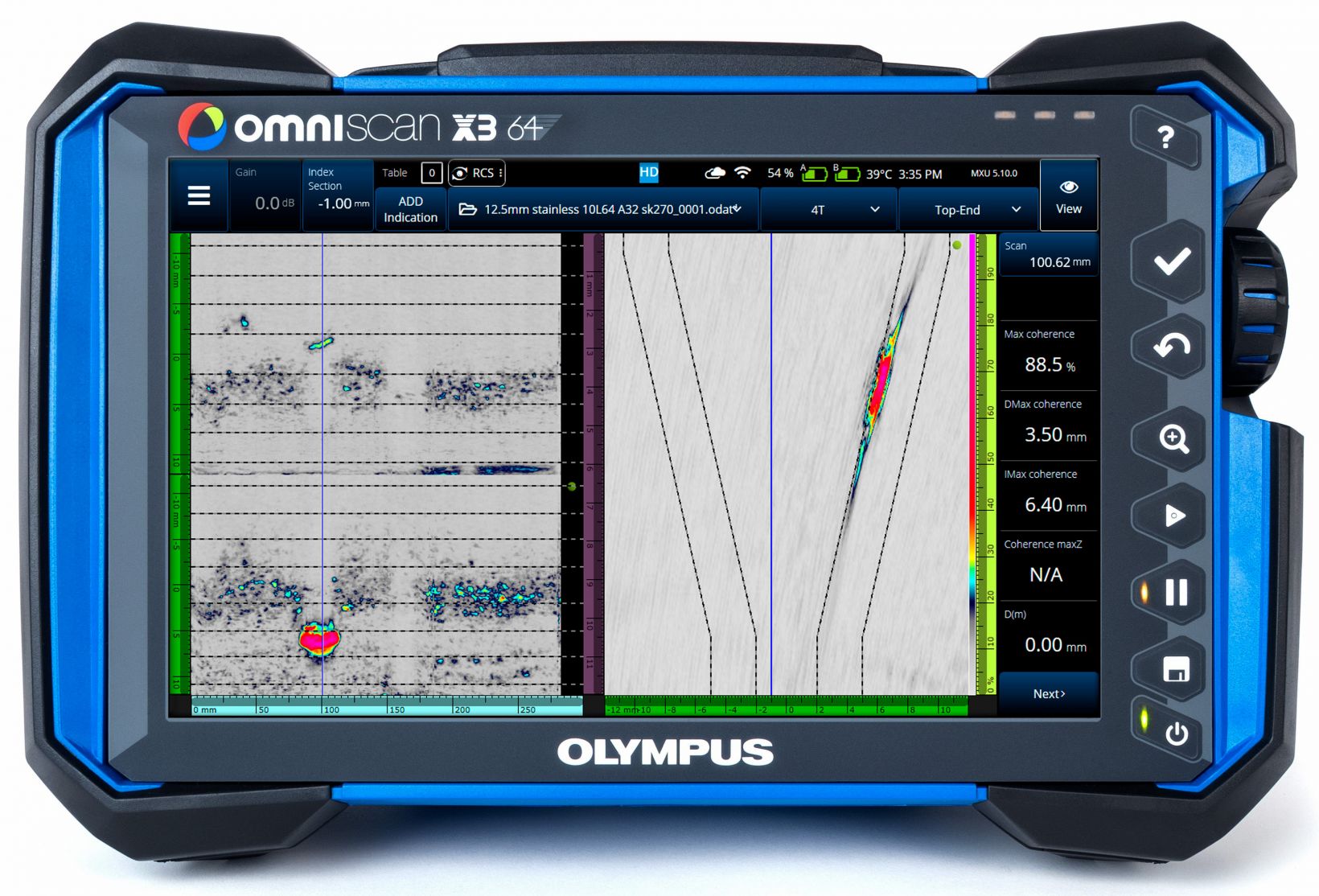
With the release of MXU 5.10 software, the OmniScan™ X3 64 flaw detector gains a new advanced ultrasonic inspection technique: phase coherence imaging (PCI). As soon as your OmniScan X3 64 unit is updated, you can start taking advantage of PCI to achieve live total focusing method (TFM) images with unprecedented clarity and sensitivity to small defects.
How PCI Works and How It Differs from Other Ultrasonic Techniques
PCI is an amplitude-free technique. Its signal processing is based exclusively on the phase information of the elementary A-scans used to generate a TFM image.
How PCI works:
- First, the acquired A-scans are normalized.
- Then, the phase distribution of each A-scan is compared for each position in the TFM zone.
- For a given position, the higher the level of coherence between the A-scans, the stronger the signal response for that position (with a maximum of 100%).
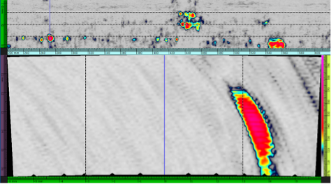
- Reflections and diffractions from defects result in a coherent response, compared with the incoherent response of acquired signals from high-frequency background noise. This makes identifying defects very easy, especially for small defects in noisy or attenuative materials.
In our testing, PCI has proven to provide excellent results for many challenging use cases, as well as improved results for common use cases such as weld inspections. Here are 5 advantages that make this new inspection technique so powerful.
1. Live 2D Images Using Signal Phase Information
Ultrasonic testing (UT) users may be familiar with exploiting the signal phase information to identify and size defects using techniques such as time-of-flight diffraction (TOFD). Such techniques are effective for identifying defects that are very small or in an orientation that has a poor response with the phased array (PA) technique.
That said, TOFD has two main disadvantages:
- It’s impossible to locate a defect in the index axis without scanning multiple index positions.
- The amplitude is still required to visually identify the phase changes to size defects.
PCI is a powerful technique for identifying defects that are poorly oriented or very small, such as high-temperature hydrogen attack (HTHA), but it avoids the problems associated with TOFD. Because the TFM acquires the volumetric data, the defects can be located and sized in all directions. The final image using the PCI mode is also completely independent of amplitude.
This makes the analysis easier as it removes the need to scan at multiple index points. And, since PCI on the OmniScan X3 64 flaw detector generates a live image, it doesn’t require the full raw data for post-acquisition processing.
2. It’s Impossible to Saturate the Signal
One of the challenges with amplitude-based techniques is signal saturation. Despite calibrations and gain adjustments during the setup, it is still possible that certain reflectors saturate the signal. This can be due to their size, type, or orientation compared to a side-drilled hole (SDH) in a calibration block or another known reflector.
Since PCI is based on the variance of the statistical distribution of the elementary A-scans for a specific point in the image, the coherence level cannot exceed 100%. Even if the signal of the elementary A-scans is saturated, this will have no impact on the final PCI data because only the phase information is considered and accessible.
This makes preparing for an inspection easier and faster since the scan quality is less sensitive to the configuration. After the wave sets are chosen and the voltage is set to 160 Vpp (voltage peak-to-peak), everything is good to go.
3. No Need to Preadjust the Gain to a Known Reflector
PCI is a technique that is entirely amplitude free. This means that the setup step where you use a known reflector in a calibration block to adjust the gain is rendered unnecessary. When you select “Phase Coherence” mode in the OmniScan X3 64 setup parameters, you’ll see that the gain adjustment is blocked since the amplitude is not considered for the final PCI data.
With the need for gain adjustment eliminated, the time and effort required to create a setup that provides a high-quality image is greatly reduced. Gain readjustment between scans based on the types of reflectors found is also no longer necessary, reducing the need to repeat TFM scans to make sure that the data is valid.
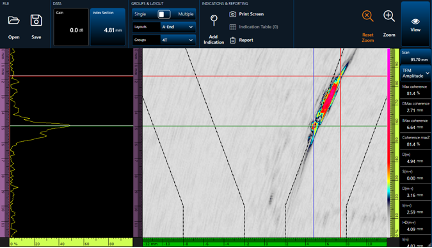
The sizing accuracy of a PCI setup can still be validated, but with a notch sample. By using the peak of the tip diffraction response from the notch, the defect height can be measured with the cursors.
4. More Consistent Results and Easier Sizing
Since PCI setups are easier and faster to create with fewer parameters for the inspector to configure, the technique enables better consistency between inspections and different inspectors. Since it’s impossible to saturate the signal during the scan and because the gain has no influence on the signal, there are fewer manipulations that could change the outcome during the analysis.
To size a defect, the inspector only needs to find the hot spots from the tip diffractions and place the cursor on the maximum of these hot spots. These resulting readings provide the size of the defect, and there are no adjustments that need to be done before each sizing. The process is expedited as well as easier.
If the same probe is used, the defect size will remain the same between each scan.
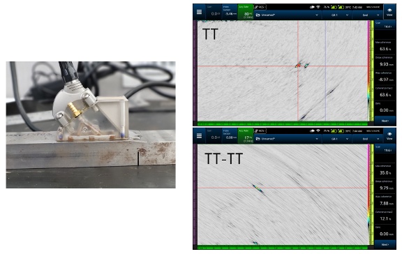
5. Fewer Groups Required for the Same Zone Coverage
The Acoustic Influence Map (AIM) tool in the scan plan is still used with PCI. The advantage of PCI versus conventional TFM is that the variations in the signal amplitude displayed by the AIM are irrelevant. Where the AIM shows the signal amplitude distribution in the part, the PCI will have good results, even if the returned amplitude is low.
This is a side effect of the amplitude-free nature of PCI. The coherence can be evaluated even if the amplitude is weak since the signal is normalized before the phase is evaluated. Even more important, the position of a defect within the TFM zone will have less impact on that signal coherence than the amplitude.
Tip diffractions can often be lost in the background noise when using conventional TFM or phased array. PCI, on the other hand, highlights these diffractions, making them stand out even when they would not be evident with conventional TFM or PA.
All of these factors result in fewer groups being required for the same zone coverage.
Because PCI is not an amplitude-based technique, you need to modify your approach when selecting your configuration and setup parameters. It's different than other UT methods you may be used to using. Read our helpful Getting Started with Phase Coherence Imaging (PCI) guide for our recommended best practices, consult our FAQs about PCI, or contact your local Evident Industrial representative to schedule a demonstration.
Blog post updated October 3, 2022, with additional information about PCI.
Related Content
Getting Started with Phased Coherence Imaging (PCI)
5 Pitfalls to Avoid When Performing Your Next TFM Inspection
Get In Touch