Angled Linear Scans
A linear scan can also be programmed at a single fixed angle, much like the beam from a conventional single element angle beam transducer. This single-angle beam will scan across the length of the probe, allowing the user to test a larger width of material without moving the probe. This can cut inspection time, especially in weld scanning applications.
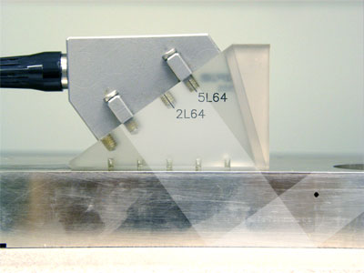
In the example above, the beam is sweeping across the test piece at a 45 degree angle, intercepting each of three holes as it moves. The beam index point, the point at which the sound energy exits the wedge, also moves from left to right in each scan sequence. The A-scan display at any given moment represents the echo pattern from a given aperture.
In any angle scan not involving very thick materials, it is also necessary to consider the actual position of reflectors that fall beyond the first leg, the point at which the beam first reflects from the bottom of the test piece. This is usually a factor in tests involving typical pipes or plates. In the case below, as the beam scans from left to right, the beam component from the center of the probe is reflecting off the bottom of the steel plate and hitting the reference hole in the second
leg.
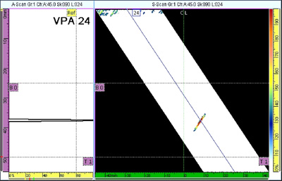
The screen display has been set up to show by means of the dotted horizontal cursors the relative positions of the end of the first leg and the end of the second leg on the image. Thus, this hole indication, which falls between the two horizontal cursors, is identified as being in the second beam leg. Note that the depth scale on the left edge of the screen is accurate only for the first leg. To use the scale beyond that, a correction must be applied. In the second leg, it is necessary to subtract the apparent depth as read off the scale from twice the thickness of the test piece to get the true depth of an indication. For example, in this case the actual depth of the second leg indication in the 25 mm thick plate is 38 - (2 x 25), or 12 mm. In the third leg, it is necessary to subtract twice the thickness of the test piece from the apparent depth of the indication to obtain true depth. Most instruments are able to do this automatically and display the result, as seen in Section 5.6.
Continue on to
Focal Law Sequence>>