Application:
Small-diameter, thin-walled, austenitic steel inspection of pipes, where standard linear shear-wave inspection is not possible.
Problem:
Standard linear shear-wave inspection cannot adequately meet the demands of this application. The acoustic characteristics of small-diameter, thin-walled, welded pipes create unique requirements for dual linear arrays. To ensure that focusing occurs in the desired zone, a different wedge roof angle is required for each diameter.
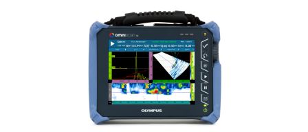
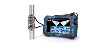
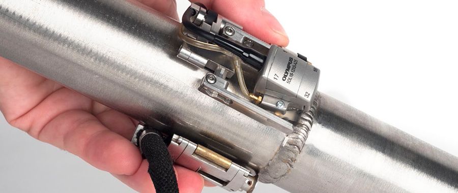
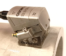
Solution:To address the need for different roof angles, Olympus created a dual linear array with variable roof angles, assembled in one standard housing. This probe adapts to wedges included in a package covering a range of 1 in. OD to 4.5 in. OD, attaches to the COBRA® small-diameter pipe weld scanner, and can be operated using the OmniScan® SX flaw detector. This package offers a solution for inspections where linear shear waves cannot detect flaws in noisy or attenuative materials. | 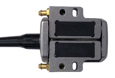 |
| Item Number | Part Number | Description |
| Q3301132 | 5DL16-12X5-A25-P-2.5-OM | Standard phased array probe, 5 MHz, dual 16 element arrays, 12 × 5 mm total active aperture, 0.75 mm pitch, 5 mm elevation, A25 case type, impedance matching to Rexolite®, PVC sheathing, 2.5 m cable, one (1) OmniScan connector. |
| Q7201159 | SA25-DN70L-Kit | One (1) SA25-DN70L flat wedge and nine (9) SA25-DN70L curved wedges to cover nominal pipe sizes (NPS) from 0.84 in. OD to 4.5 in. OD. Features IH option (irrigation and scanner holes). Fits A25 dual array probes. IMPORTANT NOTE: Focal laws for the OmniScan® using this solution cannot be created in the OmniScan flaw detector; they must be created using NDT SetupBuilder (TomoView™ can also be used). This solution will increase minimum height clearance required for use of the COBRA scanner. |
| U8750063 | COBRA-HALF | One-sided COBRA scanner package for 0.84 in. OD to 4.5 in. OD pipe inspection using one probe including irrigation parts and setup templates. 2.5 m encoder cable with a LEMO® connector compatible with the OmniScan MX2 and SX. NOT INCLUDED: Wedges and probes. |
| Q1000036 | OMNISXPA1664PR-A25-SA25 |
OmniScan SX and A25 COBRA scanner DLA promotional kit. Includes OmniScan SX portable 16:64PR phased array acquisition unit (including one UT conventional channel) with: AC adaptor, battery, small carrying case, SD™ card, USB flash drive, two (2) anti-glare screen protectors, hard copy of User’s Manual, USB key including OmniScan software User's Manuals, 1-year warranty. Also includes the following items: (1) OmniPC™ HASP key with OmniPC and NDT SetupBuilder (OMNIPC-A) -(1).
+ One-sided COBRA scanner package for 0.84 in. OD to 4.5 in. OD pipes (COBRA-HALF) -(1) 5 MHz, 16-element dual linear array probe, A25 housing for COBRA scanner (5DL16-12X5-A25- P-2.5-OM) (1) A25 series wedge kit, including one (1) flat wedge and nine (9) contoured wedges (SA25-DN70L-KIT) -(1) ES BeamTool version 8 HardLock (HASP key) package for PA technique development (SOFT-ESBEAM8HL). |
Set UpTo set up the solution
|  |
The result should be two peaked reflectors at the weld centerline of the inspection.
 | 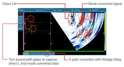 |
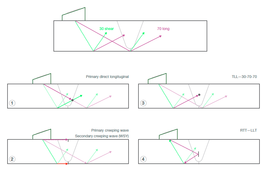
Below is a diagram of the possible signal paths of the longitudinal dual linear array. If the gates are set up properly, the A-gate will display techniques 1 and 2 traveling at the longitudinal compression velocity and will plot in the weld overlay at the correct volumetric position. The B gate will display techniques 3 and 4 containing at least one shear-wave leg and, even though it will not plot correctly, it is still useful for flaw detection and length sizing.
Results:
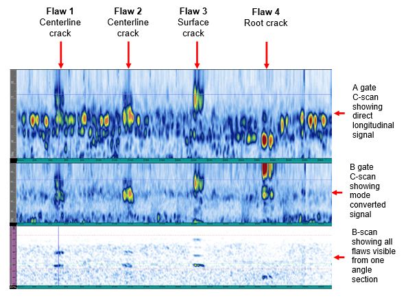
Using the calibrated setup, we scanned and recorded data. We found that the A gate recorded the weld geometry along with signal responses from four flaws in the pipe. Changing the C-scan to display the B gate revealed that the flaws were easily identified in positions along the scan axis when viewing the mode converted signal.
We then observed each flaw in the A-C-R-S view. This allowed us to view each indication along the scan access, the A-scan where the cursor is placed, and the R/S scan showing where the indications are positioned* within the weld. We observed the data in the A gate to verify whether it plotted accurately, keeping in mind that additional indications appear from mode converted signal.
*The position of the indication is only accurate if the direct longitudinal wave breaks the threshold of the A gate.
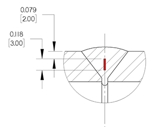
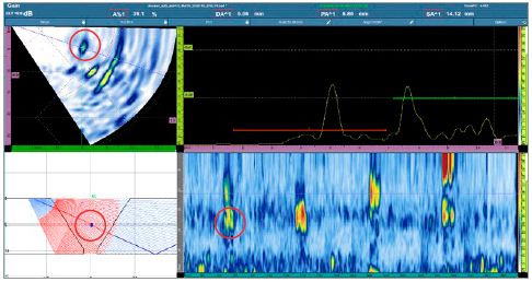
Flaw 1 is a centerline crack, and it was detected in both the A and B gates. We can observe the centerline crack, plotted accurately, in the weld volume just above the root geometry. There is also a secondary mode converted signal that is out of position but useful for flaw detection and length sizing on the scan axis.
 |  |
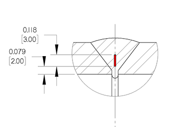
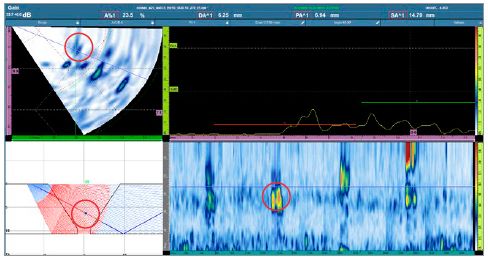
Flaw 2 is another centerline crack that is clearly detected with the mode converted signal but appears very weak in the direct longitudinal. In this case, you can see that the flaw is displayed at 23.5% amplitude in the center of the weld.
 |  |
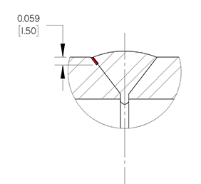
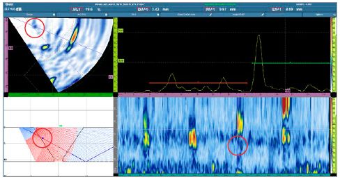
Flaw 3 is an outside fatigue crack that is along the weld bevel. The indication is displayed very clearly in the mode converted data but only appears at 19.6% amplitude for the direct longitudinal wave.
 |  |
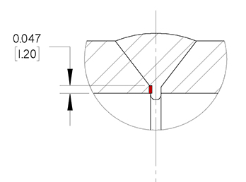
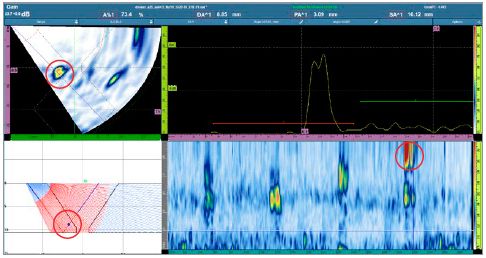
Flaw 4 is an inside fatigue crack along the weld root. It shows up just inside the second leg of the longitudinal signal and plots correctly on the weld overlay.
 |  |
Conclusion
The A25 dual linear probe is able to inspect thin-walled, small-diameter austinetic welds. Using gates positioned to display all modes of signal ensures good detection and length sizing of flaws. Advanced understanding of echo dynamics, dual linear signal modes, and probe calibration are critical to successful inspection.