Long Seam Weld Inspection Using the AxSEAM™ Scanner
Abstract
Long seam welds are challenging to inspect using conventional phased array ultrasound testing (PAUT) because of their thin wall thicknesses, the vertical weld bevel orientation, and the pipe curvature. The ultrasonic beam orientation is along the pipe curvature, which greatly affects the acoustic focusing capabilities and hence reduces the probability of detection and the ability to correctly characterize a flaw. This paper presents a new long seam weld scanner, the Olympus AxSEAM™ scanner, that facilitates the mechanical setup and scanning action for long seam weld inspection. Some guidelines for scan planning are given herein, both for conventional phased array and for total focusing method (TFM) imaging. The Acoustic Influence Map (AIM) scan planning tool for TFM is also presented, which enables the operator to properly select the probe, wedge, and acoustic imaging path in function of the flaws to be detected. Experimental results are given showing a comparison between PAUT and TFM imaging.
1.0 Introduction
Electrical resistance welding (ERW) is a manufacturing process that dates back to the early 1900s. The initial process used low-frequency alternating current (AC) while the more recent technique, circa 1970, uses higher frequency AC current. Welds built from the older process are prone to seam corrosion and hook cracks around the weld region [1] due to both the welding process and the steel quality used [2]. While the newer process yields a higher quality weld, older pipes are still in service and need periodic examination to reduce—and ideally eliminate— the risk of critical failure, which can result in an oil spill [3].
Inspection of the longitudinal (or long) seam welds in pipes using phased array ultrasonic testing (PAUT) has proven to be challenging for diverse reasons. For example, regarding the acoustic beam behavior, the curved interfaces at which the ultrasonic beams are refracted or reflected causes the energy to diverge, reducing the characterization capabilities. Also, the relative orientation between the pulse-echo acoustic beam and the flaw does not always allow for optimal energy reflection to the probe. Considering the analysis, a standard sectorial scan representation of the signals makes it difficult to determine the position of the various detected indications in the part volume since the usual scale and cursor are not related to the part and weld geometry. In this respect, the total focusing method (TFM) [4–8], a recently accepted technology [9, 10], might be used to improve imaging quality and characterization.
In regards to the mechanics, positioning the probe at the desired distance from the weld centerline as well as applying a constant and minimum pressure on the probe is a little more intricate for long seam weld inspection than for girth weld inspection. In the latter case, numerous manual and semiautomated scanners exist. These scanners are typically simple to use, in part because the wheels and the probe configurations are not affected by the pipe radius. This differs from a long seam scanner’s configuration in which the wheels and bottom face of the wedges are positioned along a curved surface.
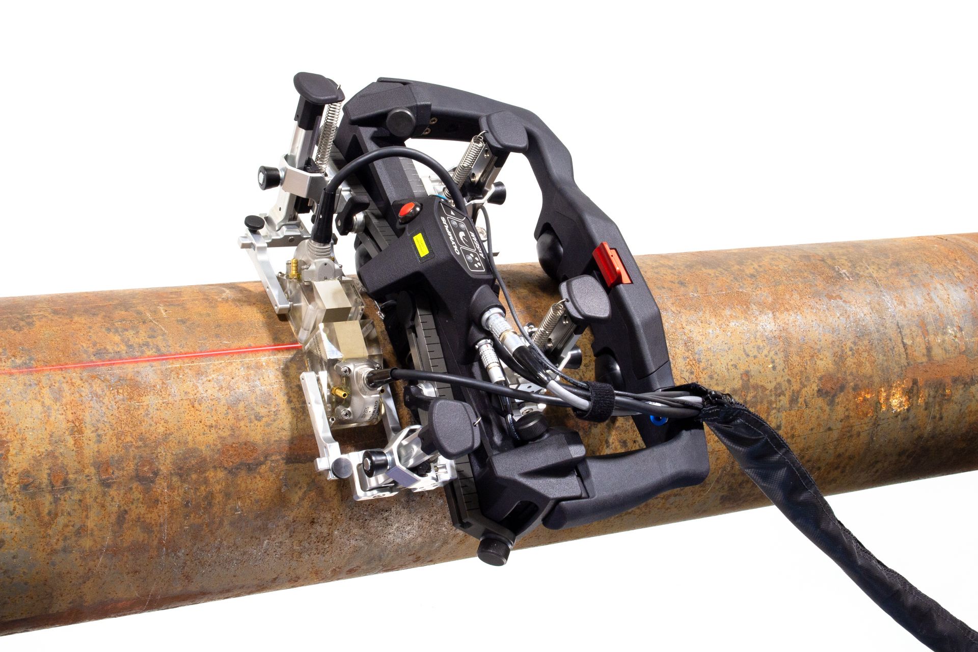
Fig. 1 – The AxSEAM™ scanner in an axial scanning configuration on an 8 in. OD pipe section
This paper presents a scanner and software solutions for long seam weld inspection. The objectives of the AxSEAM™ scanner (Fig. 1) and the OmniScan™ X3 flaw detector’s software tools are to simplify the mechanical setup and scanning process for this inspection application and to increase flaw detectability and characterization through better scan planning and imaging. In section 2, the Olympus AxSEAM scanner is presented. While designed for long seam inspection, it also enables girth weld inspection on a specific diameter range and incorporates features such as coupling and speed check LED indicators, a start acquisition button, and a laser guide. Section 3 presents some scan planning tools and guidelines for both conventional PAUT and for TFM. Section 4 provides experimental results, including a concise comparison between PAUT and TFM imaging and presents new software tools that enable easier indication characterization. Finally, a brief conclusion is provided.
2.0 Scanner Description and Features
Inspecting pipes in the longitudinal direction can be more challenging than circumferential scanning as a variation in pipe diameter has a greater impact on how the scanner and probes fit on the surface. This has been addressed in the design of some older scanners by adding several complex adjustments, at the expense of simplicity. Olympus developed the AxSEAM™ scanner with a focus on easing the setup by minimizing the adjustments required when changing pipe diameters, probe separation, or scan orientation. The AxSEAM scanner also includes new features that enable one operator to perform the scan without needing to directly manipulate or monitor the acquisition instrument.
2.1 Specifications
- Quickly and easily set up on a wide range of pipe diameters:
- Longitudinal welds: 152.4 mm (6 in.) OD up to flat
- Circumferential welds (Fig. 2)
- 254 mm (10 in.) OD and up with 4 probes
- 114.3 mm (4.5 in.) OD with 2 probes
 The AxSEAM scanner on a circumferential weld with 2 probes on a 114 mm (4.5 in.) OD pipe | 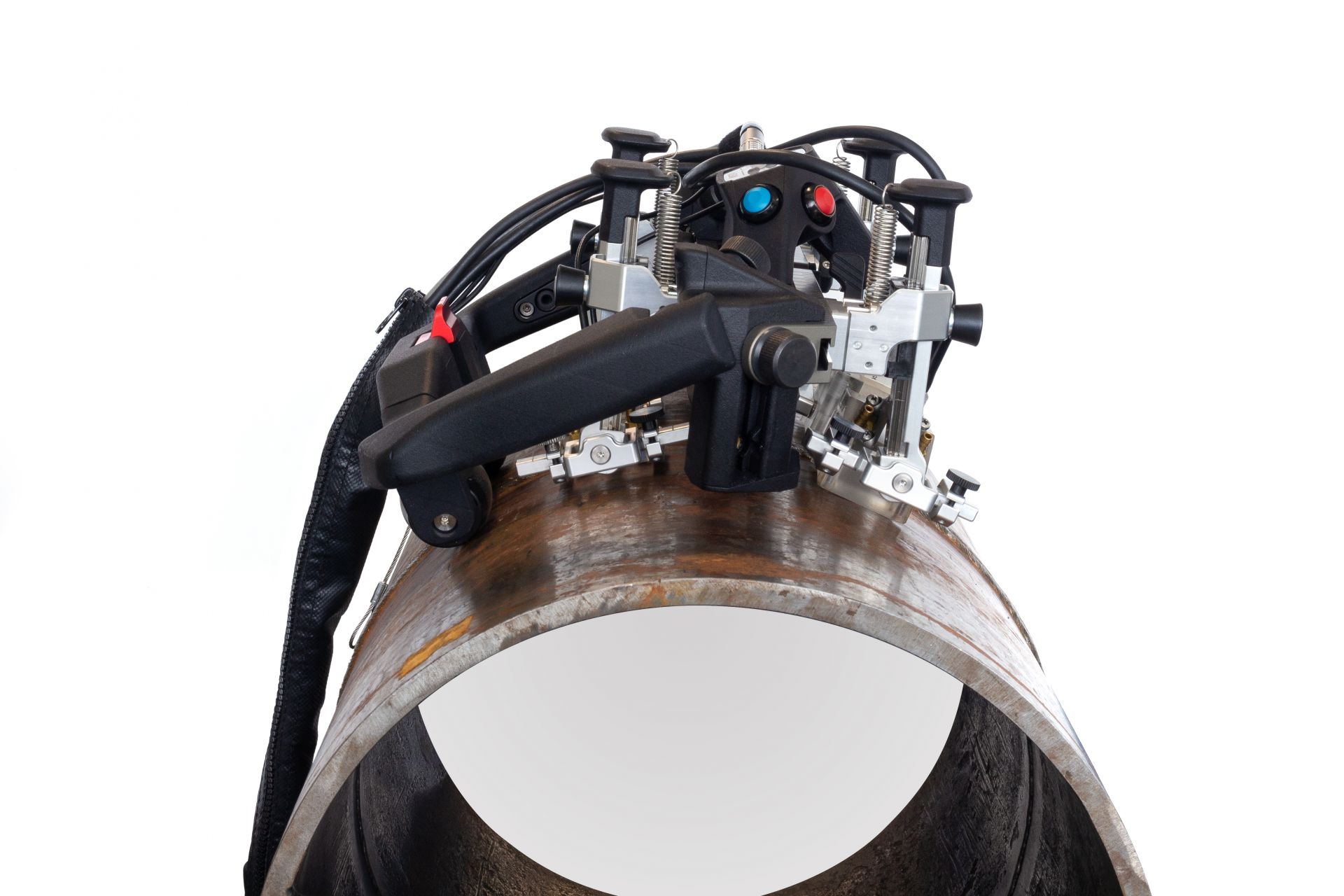 The AxSEAM scanner on a circumferential weld with 4 probes on a 324 mm (12.75 in.) OD pipe |
Fig. 2 – The AxSEAM™ scanner in circumferential scanning configurations
2.2 Key Features
The main features of the AxSEAM scanner are shown in Fig. 3 and include the following:
- Four probe holders accommodate both PA and TOFD probes to execute a multitechnology inspection, including TFM
- Patented dome-shaped wheels adapt to pipes without adjustment between changes in diameter
- Magnetic wheels and a brake system help maintain the scanner’s position on the pipe
- Intuitive tool-free adjustment mechanisms and controls
- Convenient cable management sleeve
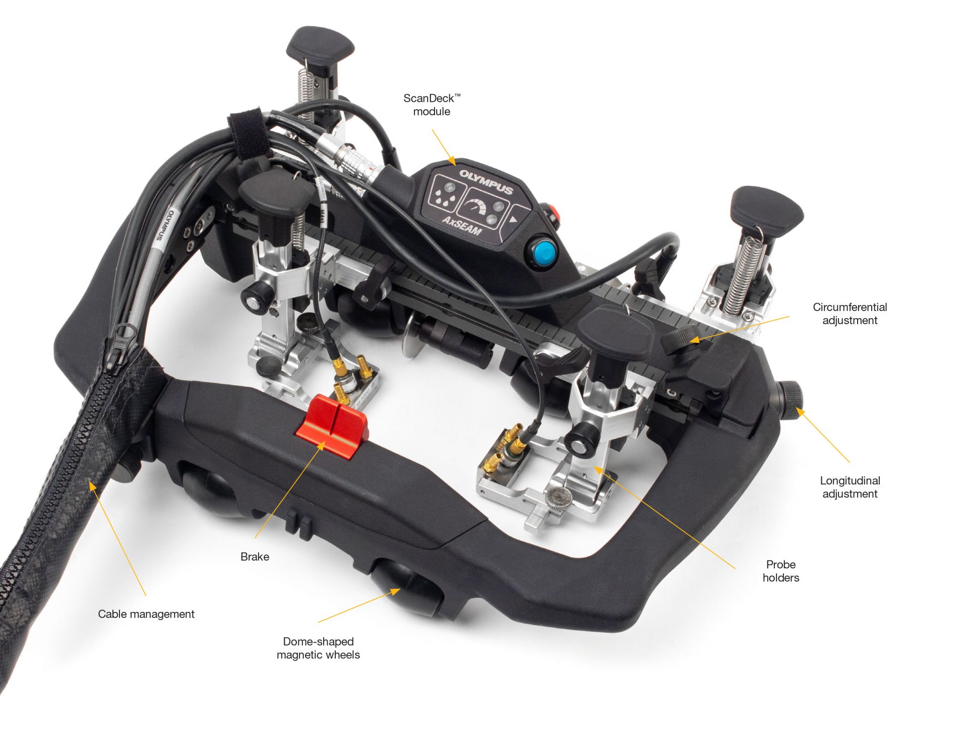
Fig. 3 – AxSEAM™ scanner features
2.2.1 Instrument Interface and Control
The AxSEAM scanner’s ScanDeck™ module (Fig. 4) provides important information to the operator directly on the scanner and enables remote operation of the instrument. It is easy to reach and in your line of sight while scanning.
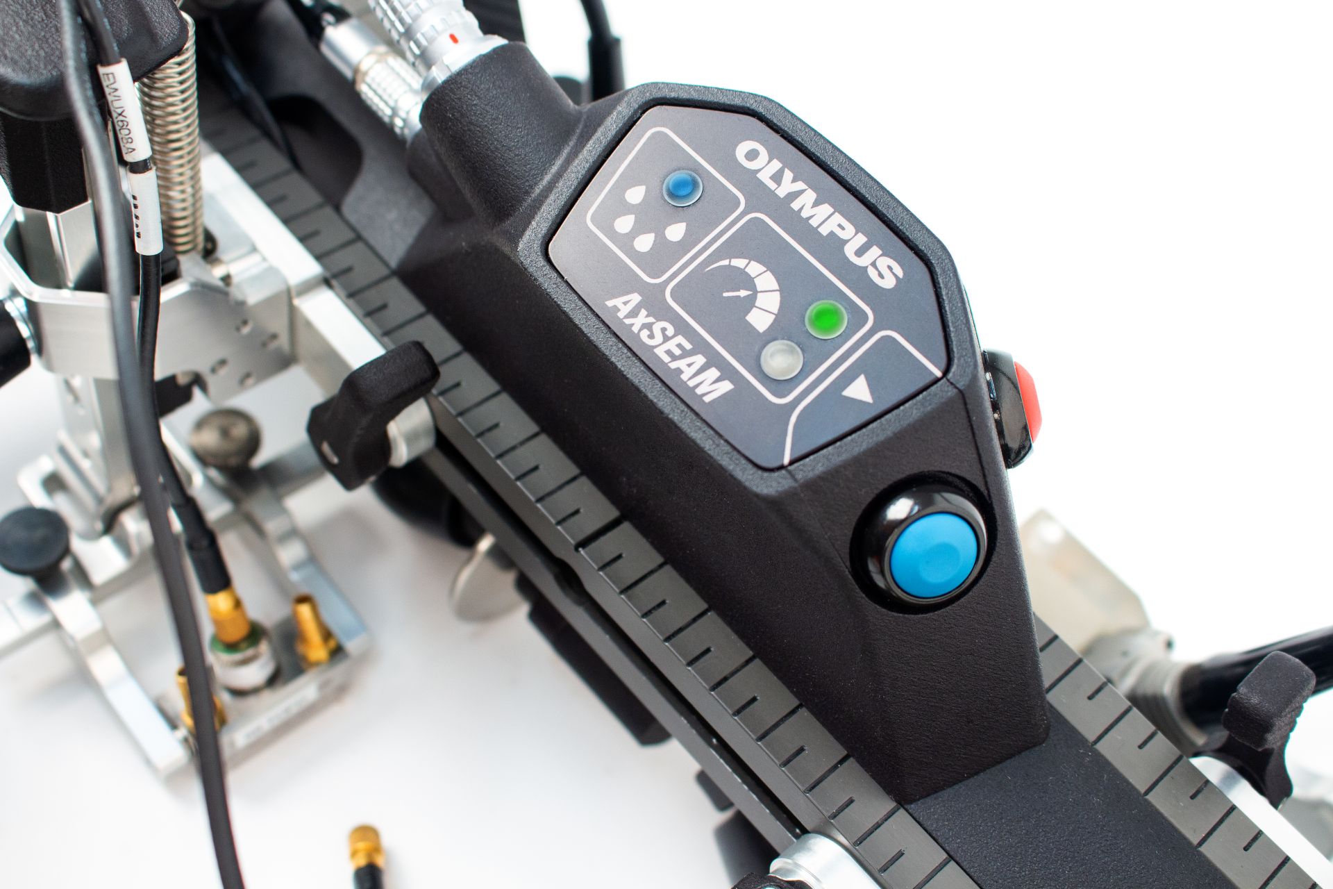
Fig. 4 – The AxSEAM™ scanner’s ScanDeck™ module
- The ScanDeck™ module contains two buttons—one button can “zero” the encoder and start the acquisition on any OmniScan™ unit and the other button activates the laser guide (Fig. 5).
- One LED indicator is linked to the OmniScan X3 unit’s phased array channels and alerts to a loss of coupling, and another set of LEDs indicate when the scanner speed has exceeded the maximum scan velocity to help prevent missed data. This feature is particularly useful for total focusing method (TFM) inspection, which can require a lower acquisition rate.
The module also integrates a laser that the operator can use to remain aligned with the weld or a mark identifying the position of the weld in cases where the weld bevel is not visible.
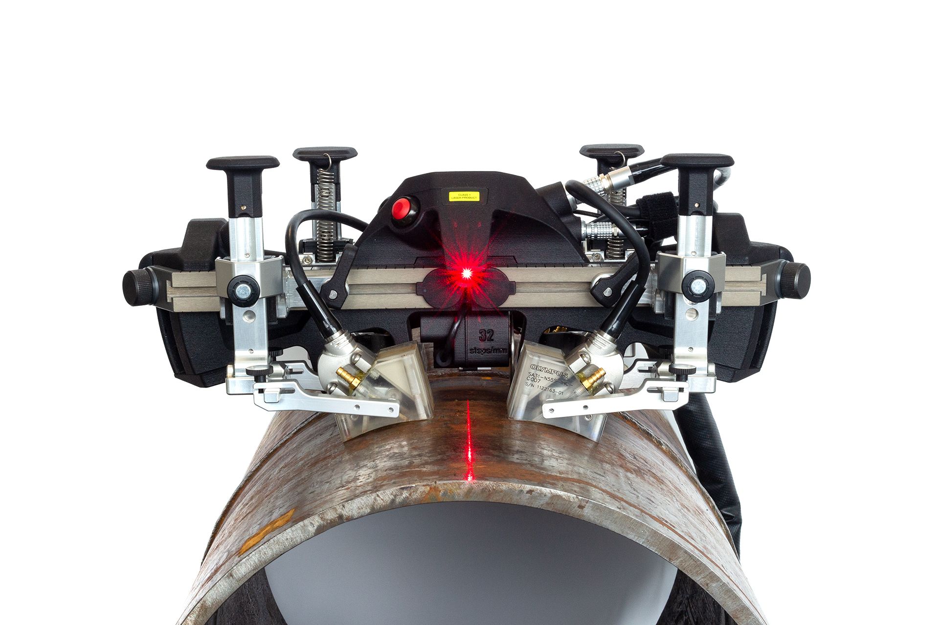
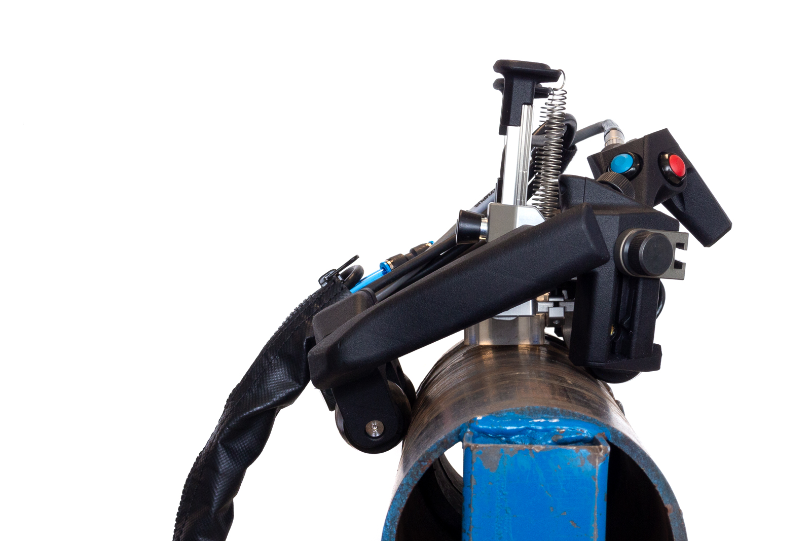
Fig. 5 – The AxSEAM™ scanner set up in an axial scanning configuration with the laser guide activated
3. Scan Planning Tools and Guideline
Scan planning is a crucial part of any ultrasonic inspection. Without an adequate scan plan, flaws can be misinterpreted or even worse, missed. The Olympus OmniScan X3 flaw detector offers simple tools for long seam weld scan planning, for both conventional phased array and for TFM inspection. This section presents some scan planning guidelines and tools the operator can use to create an optimized setup.
3.1 Conventional Phased Array
Two main criteria are used to build a good acoustic scan plan for a long seam weld inspection: weld coverage and sensitivity to the flaw. The former is relatively simple to determine from the ray tracing, even if using only the first and last ray of the sectorial—or linear—scan. The operator only needs to make sure that the weld and the heat-affected zone (HAZ) are positioned within the displayed ray-tracing zone. The latter criterion (sensitivity to the flaw) depends not only on the acoustic setup but also on the characteristics of the flaw itself. For example, a setup optimized for a volumetric flaw, such as inclusion, might not be well suited for a vertical flaw, such as an internal crack.
To increase the probability of detection (POD), the acoustic ray incidence angle on the flaws must be as perpendicular as possible to the flaw orientation. For a typical 30° V-bevel girth weld, rays from a sectorial scan with a 40° to 70° refracted angle will hit the weld bevel at a near normal orientation (see Fig. 6a). On such a bevel, flaws such as lack of fusion will have an orientation close to the bevel orientation, hence a typical 40°–70° sectorial scan will provide good detection capabilities.
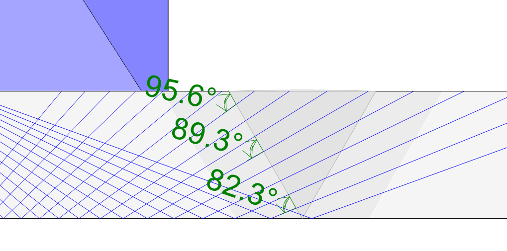 (a) Configuration on plate with a 30° bevel angle. Sectorial scan 40°–70° with an angular resolution of 2°. |
 (b) Configuration on plate with a vertical bevel (0°). Sectorial scan 40°–70° with an angular resolution of 2°. |
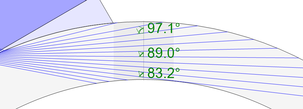 (c) Configuration on an axial weld, outside diameter of 114 mm (4.5 in.) with a vertical bevel. Sectorial scan 47°–60° with an angular resolution of 1°. |
Fig. 6 – Comparison of the beam perpendicularity to the bevel wall angle for three different part and weld configurations. Probe: 5L32-A31. Wedge: SA31-N55S-IHC. |
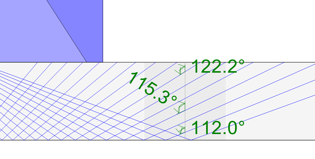
However, for long seam weld inspection the flaws are typically orientated vertically (i.e., in the radial direction, from the center of the pipe). In Fig. 6b, we see that the incidence angle of the rays of a 40°–70° sectorial scan and the vertical bevel in a plate are not close to normal, so they will probably yield a low probability of detection.
In the case of a long seam weld, the pipe’s radius of curvature plays a role in the ray incidence to the weld. As seen in Fig. 6c, the 47°–60° sectorial scan rays have a close 4 to normal incidence to a vertical bevel in a 114 mm (4.5 in.) outer diameter (OD) pipe. Hence, while vertical flaws in a plate are usually hard to detect using pulse-echo PAUT, these same flaws in a small-radius pipe can be detected. However, a broad range of pipe diameters exists, and each diameter must be treated differently. From the examples shown in Fig. 6, we see that it is quite possible that for mid-range diameters—for example, a 20-inch pipe—pulse-echo mode might not be well suited for vertical flaw detection. Other acoustic imaging paths, such as self-tandem modes where the transmitter and receiver path are different, can be used to increase probability of detection. This type of acoustic mode is already used for J-bevel circumferential weld inspection [11] using conventional PAUT, but this technique yields only a single A-scan. However, the total focusing method (TFM) enables imaging of numerous self-tandem acoustic modes. This inspection method could therefore increase the probability of detection for long seam weld inspection.
3.2 Total Focusing Method
The TFM method has some advantages over conventional PAUT for long seam weld inspection. First, the TFM region of interest (i.e., the TFM grid) can be made true to geometry. In the OmniScan™ X3 flaw detector, the TFM grid conforms to the part curvature, providing easier to interpret imaging. Another advantage is the acoustic focusing. While various focusing schemes exist for PAUT, TFM imaging is focused everywhere in the region of interest, eliminating the need to configure this parameter for the operator. And, as previously stated, another advantage of TFM is the availability of new imaging paths, such as self-tandem propagation modes, that can be used to increase the probability of vertical flaw detection. The disadvantage of TFM imaging resides in the lower acquisition rate and the fact that there are multiple images, each one associated to a different acoustic path, that need to be analyzed separately.
For scan planning, the same considerations described for conventional PAUT apply to the TFM method. The acoustic beam visualization is, however, more complex since each pixel of the TFM grid is built from a summation of numerous elementary beams. Hence, the ray-tracing representations shown in Fig. 6 are not adapted for TFM. The OmniScan X3 flaw detector offers a novel TFM acoustic modeling tool for scan planning. The Acoustic Influence Map (AIM) provides users with sensitivity maps computed using the probe, wedge, part, and flaw parameters. Such AIM models are presented in Fig. 7 for three different imaging paths (T-T, TT-T, and TT-TTT). The sensitivity index, representing the maximum estimated sensitivity for the map in arbitrary units, is provided by the AIM tool to give the user a basis on which to compare one map to another and select the optimal imaging paths for the inspection.
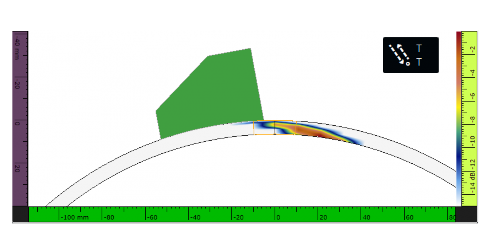 (a) TFM direct pulse-echo mode (T-T). Sensitivity Index of the AIM is 0.93 [a.u.]. |
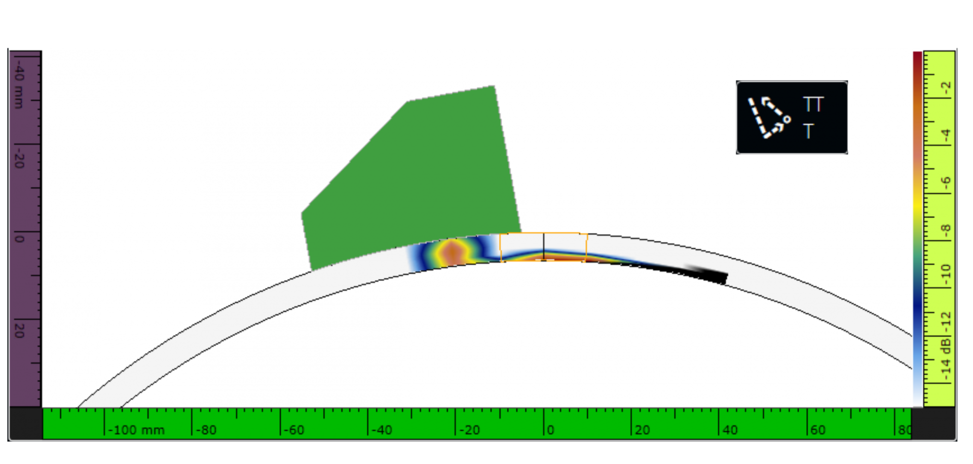 (b) TFM self-tandem mode (TT-T). Sensitivity Index of the AIM is 0.88 [a.u.] |
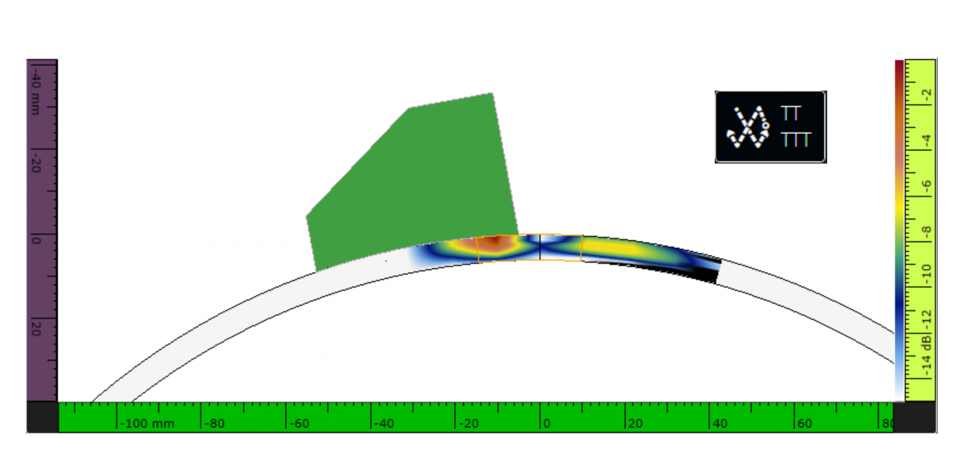 (c) TFM self-tandem mode (5T). Sensitivity Index of the AIM is 0.82 [a.u.] |
Fig. 7 – Illustration (screen captures) of AIM maps for a 12.75 in. diameter pipe of ¼ in. thickness, using a 5L32-A31 probe and an SA31-N55S-IHC-COD12.75 wedge. The sensitivity maps are computed using a vertical planar reflector. |
4. Experimental Results
This section presents PAUT and TFM results obtained on a 12.75 in. OD pipe of ¼ in. thickness. The pipe is made of carbon steel and has a long seam weld with four manufactured flaws. The pipe is 24 inches long and was scanned using the AxSEAM scanner. The probe used is the 5L32-A31 with a SA31-N55S-IHC-COD12.75 wedge. The PAUT acoustic scan plan is presented in Fig. 8 while three of the AIM models for the TFM scan plan were shown in Fig. 7.
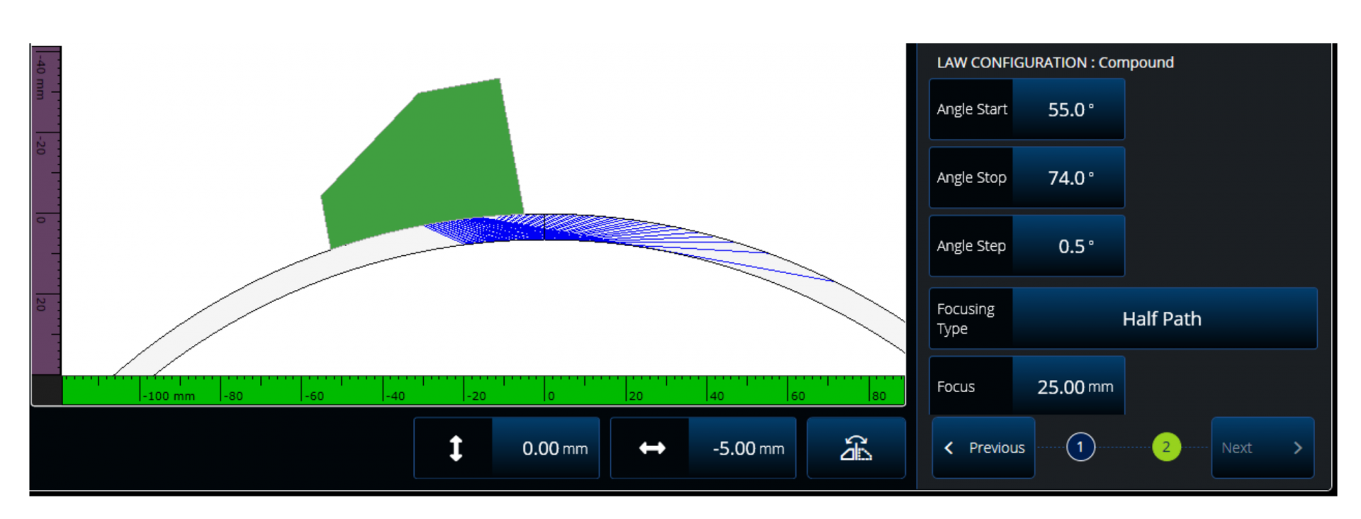
Fig. 8 – Illustration of the PAUT setup used for the experimental setup.
Figure 9 shows the resulting PAUT C-scan. Two flaws are clearly seen in the image—the first one (on the left) is a stacked vertical lack of fusion and the second one is an overtrim.
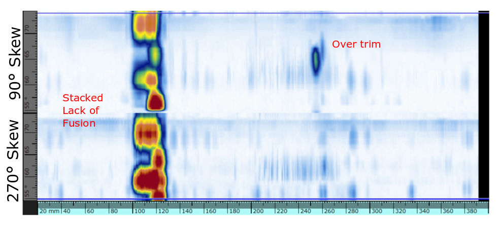
Fig. 9 – C-scan (gated data) in PAUT showing two different flaws, a stacked vertical lack of fusion (left) and an overtrim (right). Note the overtrim is only detected by the 90° skew angle.
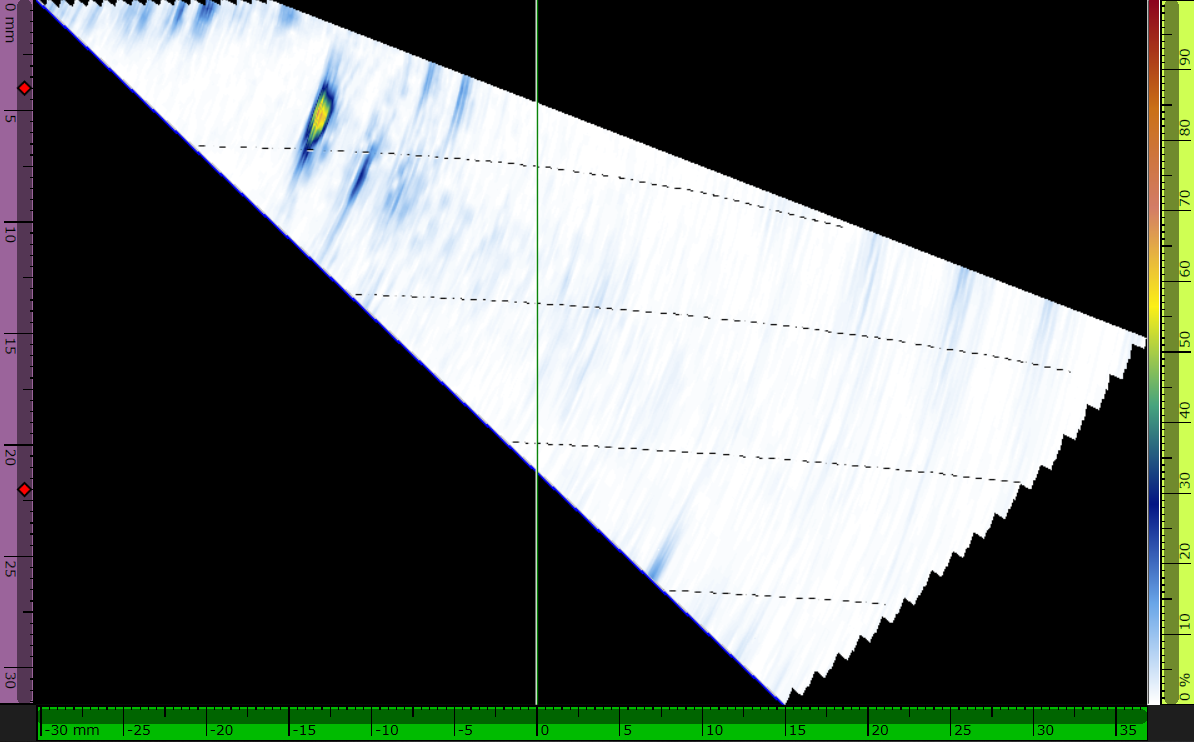
Figure 10 shows the stacked vertical lack of fusion images for both PAUT and TFM. In PAUT, both flaws are detected at various skip position. The black dotted lines indicating the skip depth positions, which are corrected for the curvature, help the operator position the indication in the part volume. The stacked lack of fusion is also detected in TFM with the T-T imaging path (direct pulse-echo). As stated previously, the TFM images are true to geometry, as seen in the image curvature of Fig. 10c.
 (a) Stacked lack of fusion |
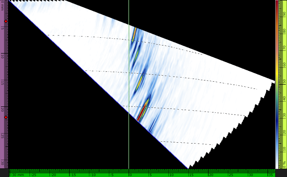 (b) PAUT |
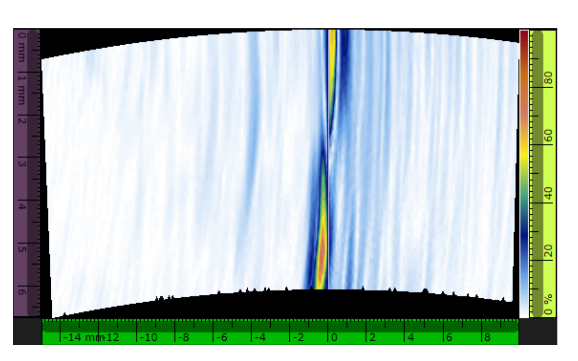 (c) TFM: T-T mode |
Fig. 10 – Results on stack lack of fusion (vertical). |
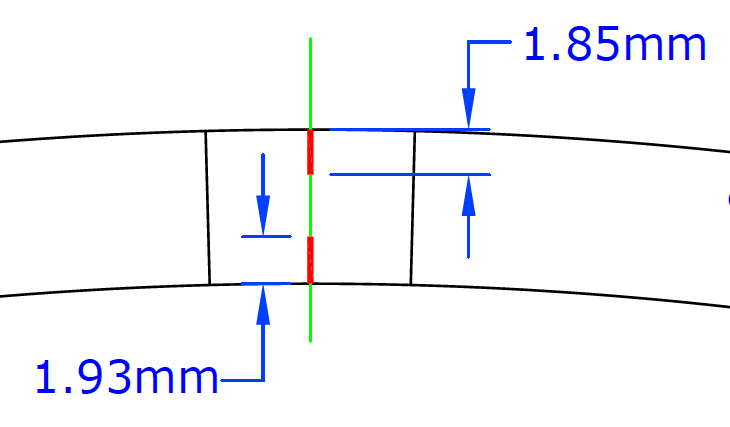
The second defect is an overtrim flaw near the HAZ. The overtrim vertical wall is detected by conventional PAUT in the first leg (see Fig. 11b) and can be easily positioned in the volume thanks to the corrected skip overlay. In TFM, two different modes can be used to image the flaw. The first one is the direct pulse-echo T-T wave set, which is equivalent to conventional PAUT. The second mode is the self-tandem TT-T wave set. With the latter, the flaw is represented as a vertical notch, which corresponds to the overtrim vertical wall.
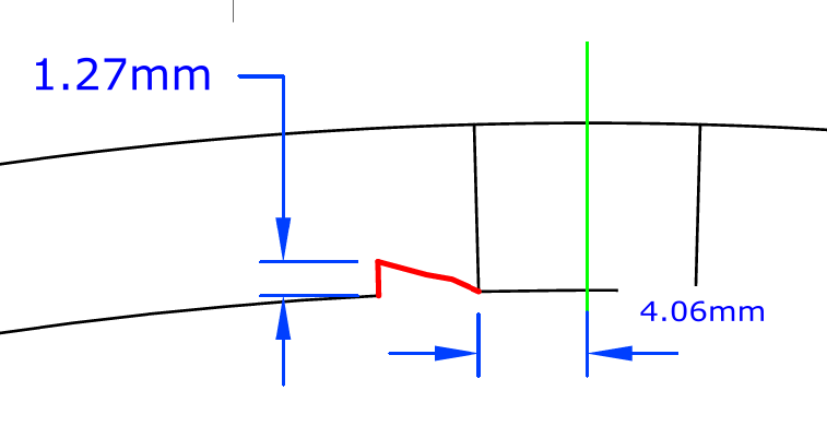 (a) ID over trim |
 (b) PAUT |
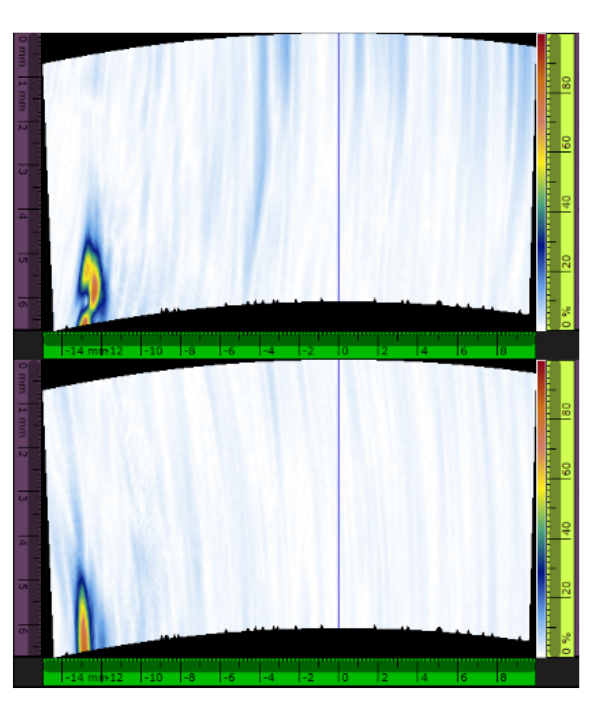 (c) TFM mode: (top) T-T (bottom) TT-T |
Fig. 11 – Results on an overtrim flaw |
5. Conclusion
Long seam weld inspection is a challenge because of the curved interfaces in the pipes and types of flaw to be detected. From a mechanical perspective, the introduction of Olympus’ AxSEAM scanner facilitates this application, offering easier setup preparation and a more reliable inspection thanks to built-in indicators that provide coupling status and velocity monitoring. The scanner is also versatile enough to be used for a wide range of pipe diameters, both for long seam and girth weld inspection.
In addition, owing to the Olympus OmniScan X3 flaw detector’s scan planning features, such as the Acoustic Influence Map for TFM imaging, and various analysis features, including the corrected skip overlay, long seam weld inspection has been rendered much simpler. It was demonstrated through experimental results that various flaws can be detected and characterized more easily with the help of true-to-geometry imaging provided by TFM.
References
[1] W. Klas, Welding Processes Handbook. CRC Press, 2003.
[2] S. Aminorroaya-Yamini, H. Edris, and M. Fatahi, “Hook crack in electric resistance welding line pipe steel,” p. 11.
[3] M. Atkins, “Failure Investigation Report - Mobil Pipeline Pegasus Rupture.” U.S. Department of Transportation, Pipeline and Hazardous Materials Safety Administration, Mar. 29, 2013.
[4] C. Holmes, B. W. Drinkwater, and P. D. Wilcox, “Post-processing of the full matrix of ultrasonic transmit–receive array data for nondestructive evaluation,” NDT E International, vol. 38, no. 8, pp. 701–711, Dec. 2005, doi: 10.1016/j.ndteint.2005.04.002.
[5] C. Holmes, B. W. Drinkwater, and P. D. Wilcox, “Advanced post-processing for scanned ultrasonic arrays: Application to defect detection and classification in non-destructive evaluation,” Ultrasonics, vol. 48, no. 6–7, pp. 636–642, Nov. 2008, doi: 10.1016/j.ultras.2008.07.019.
[6] S. Freeman, P. Li, and M. O’Donnell, “Retrospective Dynamic Transmit Focusing,” p. 24.
[7] O. Oralkan et al., “Capacitive micromachined ultrasonic transducers: next-generation arrays for acoustic imaging?,” IEEE Trans. Ultrason., Ferroelect., Freq. Contr., vol. 49, no. 11, pp. 1596–1610, Nov. 2002, doi: 10.1109/TUFFC.2002.1049742.
[8] K. E. Thomenius, “Evolution of ultrasound beamformers,” in 1996 IEEE Ultrasonics Symposium. Proceedings, San Antonio, TX, USA, 1996, vol. 2, pp. 1615–1622, doi: 10.1109/ULTSYM.1996.584398.
[9] ASME Committee, “ASME BPVC.V Article 4 Mandatory Appendix XI Full Matric Capture.” ASME, 2019.
[10] ISO, “ISO/DIS 23865 -FMC-TFM - General Use of TFM-FMC Technique.” ISO, 2020.
[11] E. A. Ginzel, Automated Ultrasonic Testing for Pipeline Girth Welds. .