Summary
Many codes allow for the substitute of one method of stated nondestructive evaluation (NDE) for another as long as certain requirements are met. Other non-code based inspections are constantly being reviewed for cost savings and other improvement to process. One substitution growing in popularity and practice is the substitution of ultrasound where previously radiographic methods were used.
Introduction
Radiography and ultrasound are two complimentary nondestructive testing (NDT) techniques. Both can volumetrically inspect welds and components for defects like cracks, lack of fusion, porosity etc. The choice of one over the other often comes to external process decisions or small variables in their ability in a particular test. In recent years the use of ultrasound where radiography was typically used has gained momentum in both practice and with major code bodies like ASME (American Society of Mechanical Engineers) and API (American Petroleum Institute). Although most codes do not specify the ultrasonic method, phased array has become the most popular choice when trying to make the replacement in processes. It is often also combined with TOFD (time-of-flight diffraction) since the modern acquisition units and scanners can accommodate both methods simultaneously. For code-based inspections historically these processes were conducted through code cases or appendixes, but after a large amount of industry practice and success they are being codified directly into the main bodies of the major code books as seen in the 2010 and beyond ASME Sec. V. Art. 4. Modern phased array equipment today is highly portable, less expensive, and easier-to-use than ever, making the opportunity to replace radiography with ultrasound easier than ever.
Typical Advantages of Ultrasonic Method vs. Radiography:
- High probability of detection (POD) especially for cracks and lack of fusion
- Ultrasound tends to detect planar flaws better than radiography in most studies
- Accurate sizing of defects height and less rejects/repair using Engineers Critical Assessment
- Ultrasound allows defect height measurement allowing volumetric consideration of flaw severity vs. just type and length
- No radiation, hazard, or additional licensing or personnel
- No screened off areas, work can go on around ultrasonic testing
- No chemical or waste material compared to film based radiography
- Real-time analysis for instant evaluation and feedback to welder
- Setup and inspection reports in electronic format compared to film based radiography
Radiography Replacement with Ultrasound Code Examples
- ASME Code Case 2235
- ASME Code Case 179
- ASME Code Case 168
- ASME Code Case N-659
- ASME Code N-713
- API 620/650 App. U
- ASME Sec. V Mandatory Appendixes
Typical Equipment and Inspection Requirements
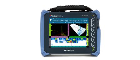
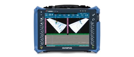
- Acquisition unit with Full Raw A-scan data retention and encoding ability (OmniScan or Focus LT)
- Scan plan and procedure showing documented inspection strategy and essential parameters
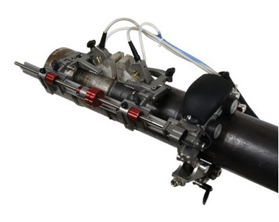
- Industrial Scanner (encoder) that repeatedly scan weld or component (Semi or Fully Automatic)
- Selection based on number of welds, pipe diameter, and other application variables
- Deliverable data
- Analysis performed on acquisition unit or post analysis software OmniPC or TomoView
- Performance demonstration for equipment, procedure, operator and inspection process
- Alternative acceptance criteria as required
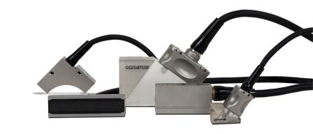
- Probes, wedges, couplant delivery and other accessories
- Proper training and certification for personnel
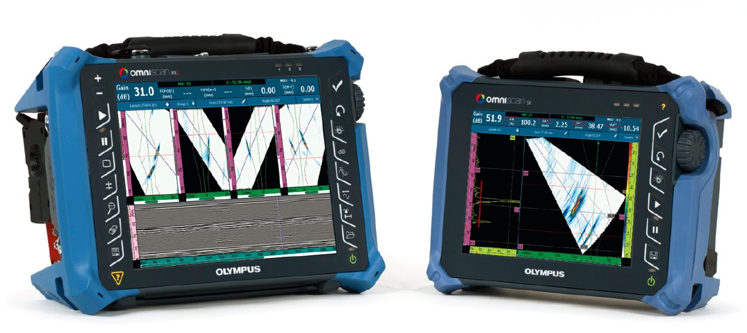
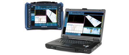
OmniScan MX2 (MultiGroup capable) and OmniScan SX (Single Group)
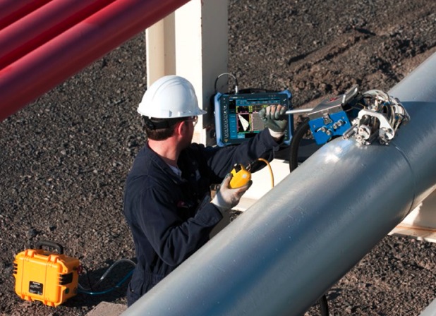 | 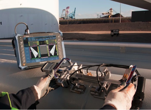 |
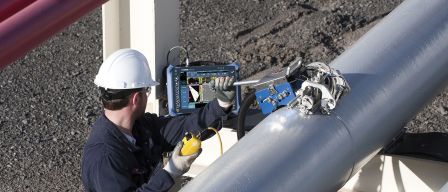
Fully automatic WeldROVER and Semi-Automatic Compact Scanner with OmniScan
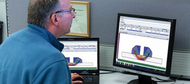 |  |
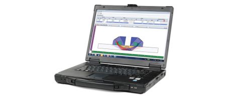
NDT SetupBuilder and OmniPC Software for design and analysis
Conclusion
Radiography replacement has become an industry trend and code accepted practice. Modern easier-to-use, less expensive portable phased array equipment and associated software has accelerated this practice in recent years. Main reasons for this continuing trend include process cost and time savings, safety of operators and those in surrounding areas, and the use of alternative acceptance criteria leading to less reject and repairs.