For piping and other flow systems, certain conditions exist that lead to corrosion and erosion in the weld root and the heat-affected zone (HAZ) of the weld. The contributing factors are often metallurgical, chemical, or flow related, and the resulting metal loss can lead to failure of the weld/base metal. The shape of the corroded or eroded weld or base metal can make ultrasonic inspection extremely difficult to apply, thus impeding accurate detection and measurement of anomalies. The time-of-flight diffraction (TOFD) technique proves to be a valid option for evaluating weld root corrosion and erosion, as well as similar conditions such as FAC (flow-accelerated corrosion). The goal of any of these inspections is to accurately measure the wall thickness, the weld, and the HAZ. The unpredictable shape of the remaining material often makes pulse-echo ultrasonic inspection ineffective.
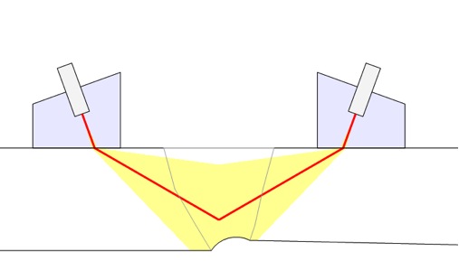
TOFD has been used for some time for general weld inspections. It has proven to be a rapid and easily deployable method with an excellent capacity for sizing. One of the inherent strengths of TOFD for detection and sizing purposes is its relative indifference to the orientation of defects because of its primary use of diffracted versus reflected energy. The TOFD technique utilizes two transducers: a transmitter transducer floods the inspected region with sound in the forward direction; on the opposite side of the weld, a receiver transducer is positioned to receive diffracted and reflected energy from the back wall or from anomalies present in the region. Common pulse-echo techniques can be misdirected by the shape of the region, resulting in imprecise measurement and assessment.
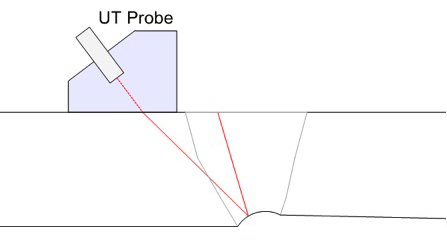
Pulse-echo shear wave beam being reflected at an off angle.
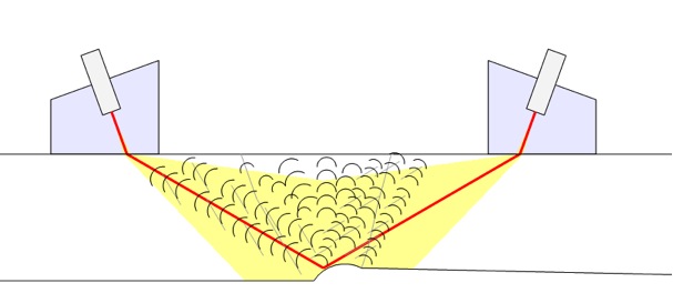
Illustration of diffracted energy reflecting off weld root/HAZ in all directions.
For these types of weld inspections, TOFD is typically performed from three positions for each weld: centered on the weld, offset to the left, and offset to the right. Scanning from these particular positions helps to achieve the best results. This method ensures detection of the highest point of material loss, determines from which side of the weld the erosion/corrosion indications are originating, and eliminates any masking caused by the back wall signal. Depending on the instrument, these scans can be run concurrently or in separate acquisitions.
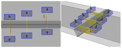
Illustration of 3 probe positions for acquisition: offset 1, centered, offset 2 (left to right)
TOFD is deployed by scanning the weld with a semiautomatic or fully automatic scanner. Scan settings are set to determine scan resolution. The resulting data file can be saved indefinitely for review and comparison to future scans. After data is acquired, it is analyzed to identify any areas of concern, either directly on the instrument or in post-analysis software. Shifts in data (time/depth) are measured in order to assess the severity of metal loss. The cursors can then be positioned to define areas for depth or thickness measurement readings. Weld defects such as porosity, lack of fusion, and cracking can also be detected when scanning for corrosion and erosion.
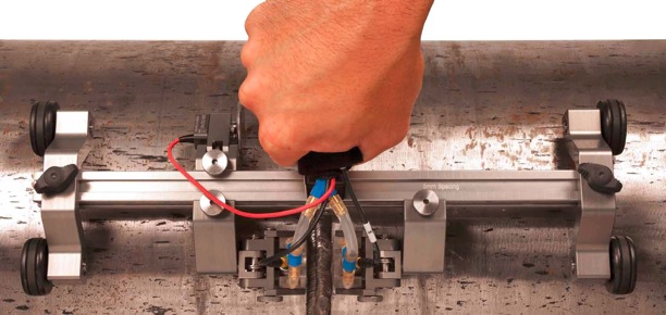
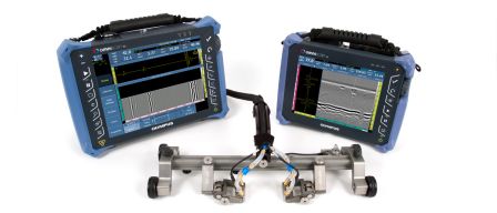
A TOFD scanner on a weld
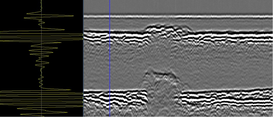
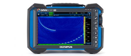
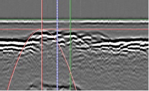
Scan of weld with cursor positioned on an uncorroded area; A-scan shows good lateral wave and back wall signal with no indications in between.
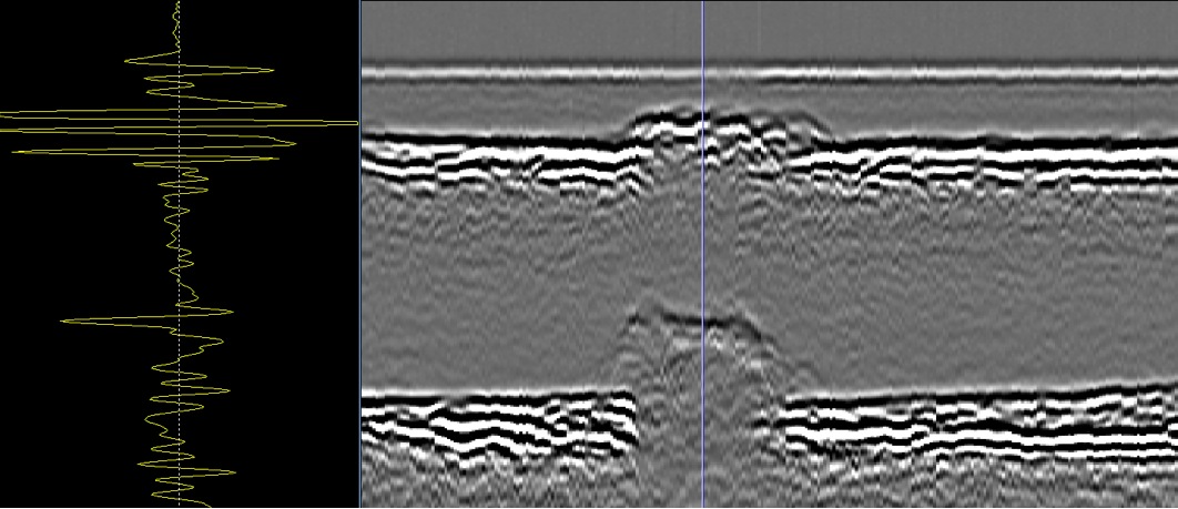
Scan of weld with cursor positioned on a corroded area; A-scan shows shift in time of back wall signal from material loss.
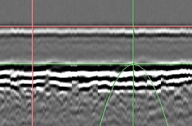 |
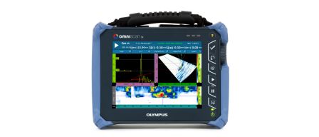
Measurement of good area shows thickness as 7.39 mm; TOFD (m-r) reading shows the distance between the positioned cursors.
 |
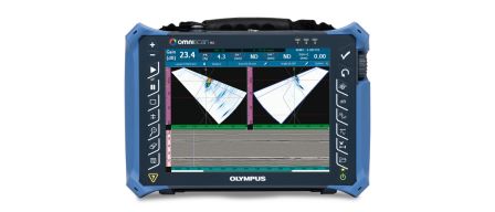
Measurement of corroded area shows thickness as 5.28 mm; cursors are positioned at top of plate (0) and highest point of material loss. In this example, there is 2.11 mm of material loss due to corrosion.
TOFD for Corrosion Measurement Equipment (Typical)
- OmniScan SX or MX2 (PA or UT models, depending on the number of channels desired and if phased array capability is needed).
- TOFD circumferential scanner (HST-Lite or similar, depending on the desired number of probe holders and other application specifics; for example, pipe versus plate).
- TOFD probe and wedges (various frequencies, angles, and materials).
- Couplant delivery system, WTR-SPRAYER-8L or similar.
- TomoView Analysis or OmniPC post-analysis software (optional).
TOFD Benefits for Corrosion/Erosion Measurement
- Rapid scanning.
- Cost effective.
- Auditable and retrievable permanent data sets.
- Accurate sizing capability.
- Excellent detection, even on irregularly shaped areas of metal loss.
- Fast post-acquisition analysis results.
- Portable and user-friendly TOFD scanning packages.