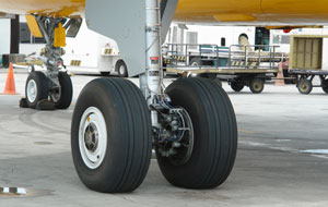
Some of the parts that have required inspection lately include landing gears, which are subject to intense stress upon takeoffs and landings. The section that must be inspected is a cylinder possessing three different diameters in the zone of interest. The best way to inspect that zone is to use a phased-array technique with steering capabilities to simultaneously fire 40- to 70-degree shear wave refracted angles in the part.
Material Requirements
Inspection Method |
자료실
Application Notes
자료로 돌아가기
랜딩 기어 검사
 In today's aerospace market, the reliability of airplanes is more than ever a prime concern because airlines companies are trying to make their fleet last longer. To reach this goal safely, these companies must perform more inspections in order to ensure customer safety.
이 애플리케이션에 사용되는 제품
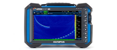
OmniScan ™ X3 시리즈의 모든 결함 탐상기는 완전한 위상 배열 툴박스입니다. 혁신적인 TFM 및 고급 PA 기능은 강력한 소프트웨어 도구와 간단한 워크 플로우로
생산성을 향상시키는 동시에 결함을 확실하게 식별하는 데 도움이됩니다.
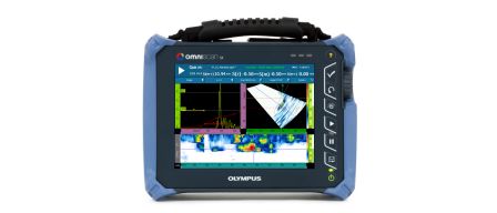
단일 그룹인 경량 옴니스캔 SX는 읽기 쉬운 8.4인치(21.3cm) 터치 스크린을 갖추고 있으며, 비용 효율적인 솔루션을 제공합니다. 옴니스캔 SX는 SX PA와 SX UT의 두 가지
모델로 제공됩니다. SX PA는 UT 전용 SX UT와 마찬가지로 P/E, P-C 또는 TOFD 검사를 위한 재래식 UT 채널을 장착한 16:64PR 장치입니다.
죄송합니다. 이 페이지는 해당 국가에서 사용할 수 없습니다.
아래 양식을 작성하여 원하는 내용을 알려주십시오.