Crevice corrosion is a known damage mechanism. In crevice corrosion, a concentration of corrosive materials or a combination of substances form a corrosive solution located at a specific point, accelerating damage. One example is the corrosion that can occur between seals on two opposing flanges with a gasket placed in-between the seals.
Corrosive materials collect within a crevice, such as between sealing surfaces and gasket material. Because the concentration of the corrosive material is in a localized area, the rate of corrosion is accelerated. Corrosion or loss of sealing area can cause loss of containment, leading to a potentially catastrophic release with loss of assets, production, and even injury to personnel.
Testing the sealing surface of flanges has become standard practice. Testing is performed in situ as part of a run and maintain program. Testing is also common as a pre-turnaround exercise to determine which flanges need to be repaired. Machining the flange face in the field is performed as an in-situ repair. Ultrasonic testing can be used to determine if the flange face has been machined and if loss of sealing area has occurred. If there is no more seal to repair, the flange must be replaced, or the seal area must be renewed using a weld build-up technique. | 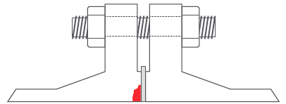 A cross-sectional view of a raised face flange. |
Caution: If the flange face has been repaired by welding and machining, then ultrasonic testing (UT) inspection might detect this weld as an interface. As the interface is detected, this signal can be misinterpreted as loss of sealing area.
Phased Array Application
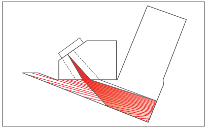
The two most common positions for placing the UT transducers are on the flange taper and between the bolt holes, as illustrated in the photographs below.
The taper areas of flanges are not always the same, so the geometry must be plotted for each flange. This step is difficult and can lead to error in condition assessment.
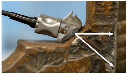 The phased array transducer is placed on the angled section of the flange. | 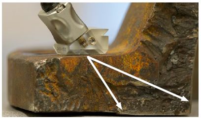 The phased array transducer is placed between the bolts. |
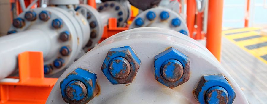
Raised Face Flange Photos
The photos below show an example of raised face flanges as applicable to piping.
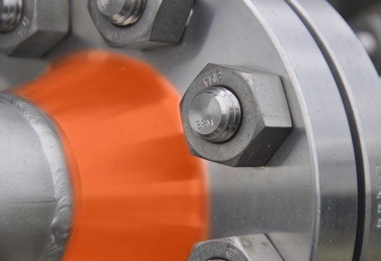 The phased array transducer can be placed on the angled section of the flange. |  The phased array transducer can be placed between the bolt holes. |
BeamTool Software from Eclipse Scientific
Using BeamTool software can help make it easier to set up phased array techniques.
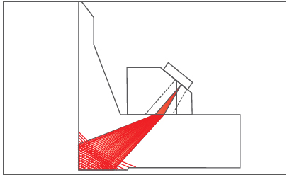
 Phased array applied with the transducer on the flange taper. | 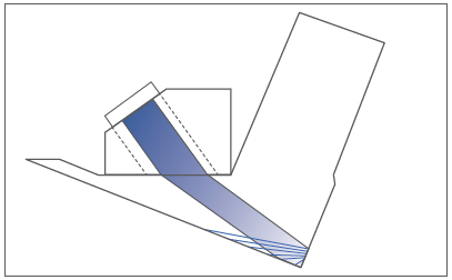 |
 Phased array applied with the transducer between the bolt holes. | 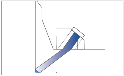 |
Industry Applications
The primary focus of this application is manufacturers and/or users of hydrofluoric acid (HF). HF units are common in refineries and chemical plants. Other types of processes can attack the flange seal, including acids, steam, and salt water.
Calibration StandardA calibration standard should be used to confirm the phased array setup. Using a duplicate of the flange (same size and weight) with targets manufactured in the raised face sealing area for UT performance demonstration is the ultimate confirmation of setup performance. Example of a calibration standard. A = 0.075 in. deep × 1.0 in. long | 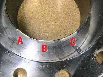 |
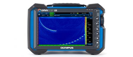
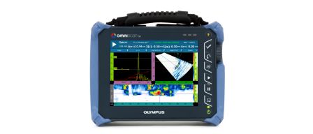
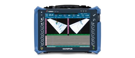
Applicable Olympus Products
Examination of raised face flanges can be performed using the EPOCH® 1000, OmniScan® MXU-M, OmniScan SX, OmniScan MX2, or OmniScan MX flaw detectors.
Small Olympus phased array probes are well-suited for flanges with smaller distances between the bolts and nuts.
Advantages
- Condition assessment of the sealing area without separating the flanges
- Cost savings to the owner/operator
- Increased safety due to the reduced potential for exposure to hazardous chemicals when separating the flanges
- Inspection can be performed while the equipment is online
- Planning for repair before TAR commences