Industrial videoscopes continue to improve with advanced features like high-resolution imaging and stereo measurement. While these advancements help inspectors obtain more accurate RVI measurements, this accuracy still relies on one thing—how precisely the inspector picks their reference and measurement points.
So, how can inspectors confidently select the correct points? The answer lies in 3D modeling. Read on to explore how it works.
The Importance of 3D Modeling for Accurate Videoscope MeasurementsWithout knowing the actual shape of the target during remote visual inspection, it can be tricky to specify the exact location of your measurement points. This is where 3D modeling comes in. 3D modeling provides various 3D views of your target to help you visually evaluate the surface. With 3D views next to the 2D views of the target, you can better understand your target and, consequently, feel more confident in your point selection. More confident point selection can help you reduce the chance of misalignment, perform faster inspections, and minimize the need to remeasure. | 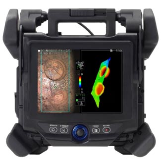 IPLEX NX industrial videoscope |
3D Modeling Views to Aid in Point Selection
Modern RVI tools like the IPLEX™ NX videoscope provide a range of 3D modeling views to help you confirm your measurement and reference points.
Here are three helpful features:
1. Rotating 3D model
One invaluable feature is the ability to rotate the 3D model to see multiple angles of your target.
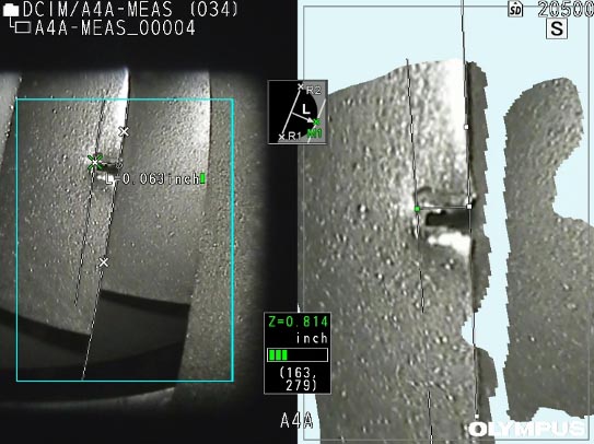
To illustrate, let’s say you’re performing a point-to-line measurement on the edge of an aircraft turbine blade. You captured the 2D picture (left) of the blade below, but it’s unclear if the measurement points are on the blade edge.
How do you confirm? Simply rotate the model and zoom in. The rotated and enlarged 3D model shows that the measurement is halfway through the blade. As a result, you can confidently confirm your points.
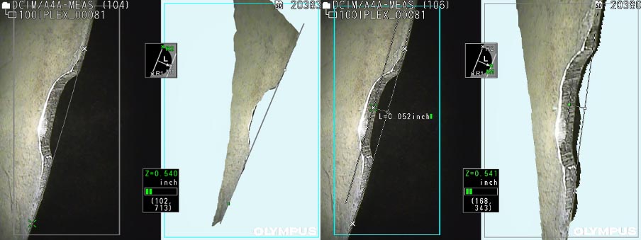
Edge of an aircraft turbine blade. By rotating the blade in the 3D model (right image), you can see the shape of the blend and use it as an aid to confirm your measurement points.
2. Depth mapping
Another handy 3D modeling feature is depth mapping (also known as color mapping). As the name implies, depth mapping helps you see differences in depth at a glance by visually mapping it out with colors.
You can use depth mapping in two ways:
- Measure the tip-to-target distance
- Measure the distances relative to a reference plane
The latter is particularly helpful in weld inspection applications because you can evaluate issues like undercuts faster. For those who are unfamiliar, an undercut is a groove melted into the base metal at the weld toe. Finding these grooves becomes a much easier task with color-coded visuals.
See just how easy it is to spot the undercut in the image below. The area below the reference plane defined by the triangle is red (the undercut), while the area in line with the reference plane is green. These clear visuals help you confirm the points on the left stereo image.
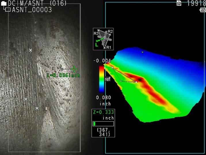
Left: Stereo image of a weld. Right: 3D model of the weld with depth mapping. The colors show the location of the undercut at a glance. Green: in line with reference plane (ref). Red: below the plane (undercut).
3. Slicing
Slicing mode offers another useful 3D modeling view. In simple terms, slicing removes objects blocking your field of view so you can focus on an area of interest. This is particularly helpful in aviation inspections where videoscopes need to fit in small gaps with limited views.
For instance, the image below shows a gouge in an aircraft inspection. The stator blade on the right blocks your view, making it difficult to take measurements. To focus on the target, simply use slicing mode to remove the unwanted stator blade from the image.
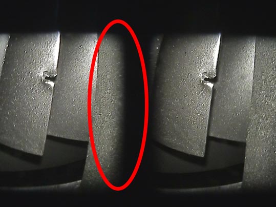
The stator blade (red circle) blocks your view.
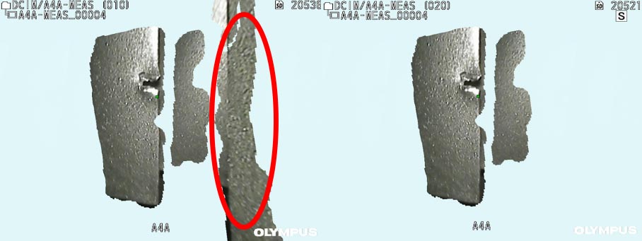
Slicing mode (S) removes the stator blade.
Now you have a profile of the 3D model (right) where you can see a distinct line on the edge of the target. This profile helps you confirm the measurement points are in the right place. You can also zoom in and out using the touch screen if you need a closer look at the model.
Learn More About 3D Modeling for Videoscope Measurements
Want to see 3D modeling in action? Watch the video below for a brief demonstration or reach out for a full demo.
You can also check out my 3D modeling presentation below, Benefits of 3D Visualization for High-Resolution Video Measurement.
Related Content
Brochure: IPLEX NX Industrial Videoscopes
Exploring the Latest Advances in RVI and 3D Stereo Measurement
Get In Touch