Calibrating pixel sizes and setting measurement parameters
In the second installment of this six-part series, we examine the second stage of the technical cleanliness workflow—image acquisition and particle measurement. This stage includes calibrating the pixel sizes and setting the measurement parameters in preparation for particle size classification. Here’s where image acquisition and particle measurement fit into the overall technical cleanliness inspection process:
- Preparation
- Inspection
- Image acquisition
- Particle detection
- Particle size measurement and classification
- Particle count extrapolation and normalization
- Contamination level calculation
- Cleanliness code definition
- Maximum approval check
- Separation of reflective and nonreflective particles
- Fiber identification
- Results review
- Reporting
Image Acquisition
Once the filter is mounted on the microscope stage, you can acquire the images needed for cleanliness inspection. It’s important to have a well-calibrated pixel size because the resulting size of the particles is sensitive to it. Image resolution is in the range of 1 µm when using a 10X objective lens.
It’s necessary to detect all particles on the filter membrane—but only once. This is why the filter membrane is split into frames with the camera’s field of view. The membrane moves, and the whole filter can be recorded.
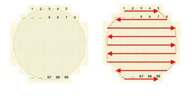
A filter membrane split into frames
There’s no need to have an overlap of two neighboring images when stitching. The mechanical precision of the motorized stage enables exact positioning of the filter membrane. About 1700 individual images are acquired for the whole filter area when using a 10X objective. This process takes less than 10 minutes, including image acquisition and analysis.
All the images need to be acquired side-by-side, and the movement must be done in image coordinates. The possible rotation between the camera (image) and stage coordinates must be compensated for during this acquisition process.
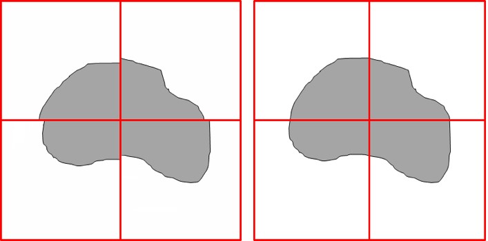
Uncorrected movement (left) and corrected movement (right)
Particle DetectionThe detection or segmentation of the image is used to combine a set of pixels in the image. This area of combined pixels is called a particle. When examining filter membranes, particles usually appear dark against a bright background. The interesting intensity range for particles usually starts at 0 (i.e., "black") and is only necessary to determine the upper intensity threshold for the particles being detected. | 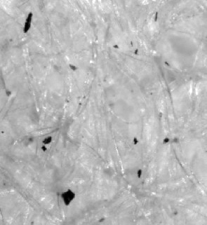 Dark particles visible against a bright background |
To investigate a complete filter membrane, it’s important that particles are also detected if they extend beyond the field of view of individual image frames. A particle might be split on two or more images but will be merged to its actual size and shape by the inspection software.
Particle Size Measurement
Each detected particle can be described by different parameters. The most important size definitions of a particle are the maximum Feret diameter and the equivalent circle diameter. Maximum Feret diameter: The maximum Feret diameter is the maximum distance of parallel tangents at opposing particle borders. This is similar to a measurement made using a caliper tool. | 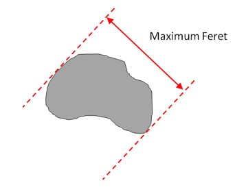 The maximum Feret diameter |
Equivalent circle diameter: The equivalent circle diameter (ECD) is the diameter of a circle that has an area equal to the area of the particle.
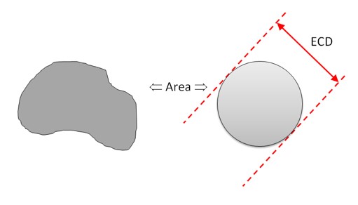
The equivalent circle diameter
Both parameters measure a length of the particle. Other particle parameters can be used to measure a particle’s area, shape, and reflectivity; these are used to recognize special particle families like fibers and reflective particles.
For some inspection standards, it’s also recommended to measure the occupancy of particles on the filter membrane. This occupancy is the sum of all particle areas, and it should be approximately 1% to 2%, but, in any case, less than 7%.
Once particles have been measured, they are ready for classification, the next phase of the technical cleanliness inspection process. Check back for Particle Size Classification and Particle Count Extrapolation and Normalization, part three of our "Breaking Down the Technical Cleanliness Workflow" blog series.
Related Content
Breaking Down the Technical Cleanliness Workflow Part 1: Preparation