Some of the parts that have required inspection lately include landing gears, which are subject to intense stress upon takeoffs and landings. The section that must be inspected is a cylinder possessing three different diameters in the zone of interest. The best way to inspect that zone is to use a phased-array technique with steering capabilities to simultaneously fire 40- to 70-degree shear wave refracted angles in the part.
Material Requirements
Inspection Method |
Material didáctico
Notas de aplicación
Regresar al material didáctico
Inspection of Landing Gear
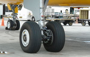 In today's aerospace market, the reliability of airplanes is more than ever a prime concern because airlines companies are trying to make their fleet last longer. To reach this goal safely, these companies must perform more inspections in order to ensure customer safety.
Productos para la aplicación
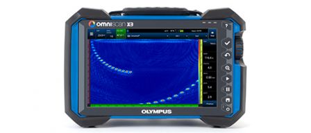
Cada detector de defectos de la serie OmniScan™ X3 es una completa caja de herramientas por ultrasonido multielemento (Phased Array). Las innovadoras y avanzadas técnicas TFM y PA permiten identificar defectos con confianza, mientras que las potentes herramientas de software y los sencillos flujos de trabajo mejoran su productividad.
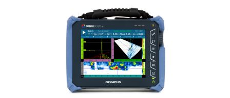
Este equipo ligero de un solo canal proporciona una pantalla táctil fácil de leer de 8,4" (21,3 cm) y soluciones bastante rentables en el plano precio-rendimiento. Viene en dos modelos: SX PA y SX UT. El modelo SX PA es una unidad 16:64PR que, al igual que el modelo SX UT [con un solo canal UT], también está equipado con una canal UT para inspecciones de pulso-eco (pulse-echo), emisión-recepción (pitch-catch) y TOFD.
Lo sentimos, la página solicitada no se encuentra disponible en su país.
Let us know what you're looking for by filling out the form below.