What Are Nonmetallic Inclusions?
Nonmetallic inclusions are compound materials embedded inside steel during the manufacturing process. Inclusions have a different chemical origin and give different mechanical properties to steel, such as formability, toughness, machinability, and corrosion resistance. As a general rule, the fewer or less severe the inclusions, the higher the quality of the steel. Therefore, analyzing and documenting nonmetallic inclusions is important for quality control.
International Standards for Analyzing Nonmetallic Inclusions in Steel
Some of the commonly used international standards for analyzing nonmetallic inclusions in steel are ISO 4967 (global), DIN 50602 (Germany), SEP 1571 (Germany), EN 10247 (Europe), JIS G 0555 (Japan), GB/T 10561 (China), and UNI 3244 (Italy). In North and South America, ASTM E45 is the dominant standard for nonmetallic inclusion analysis in steel. Quality control laboratories continue to use the ASTM chart comparison method to analyze inclusions. With this method, operators perform a visual estimate of the inclusion type and severity by comparing a live image under an optical microscope to a micrograph chart, often posted on the wall near the microscope.
Prior to the advent of digital imaging, the magnification criteria specified by the ASTM E45 standard was that inclusion ratings be performed with a compound microscope at 100X total magnification (10X objective lens and 10X eyepieces). However, this standard was updated to accommodate the growing trend in digital image analysis, stating that a resolution of 1.0 μm/pixel or better is required when using a 10X objective lens. Digital image analysis is now the preferred methodology because of its superior accuracy and repeatability, helping reduce the risk of subjectivity introduced by the human eye. Further, documenting the analysis results is seamlessly integrated into the workflow.
Inspection Method for Analyzing Nonmetallic Inclusions in Steel Samples
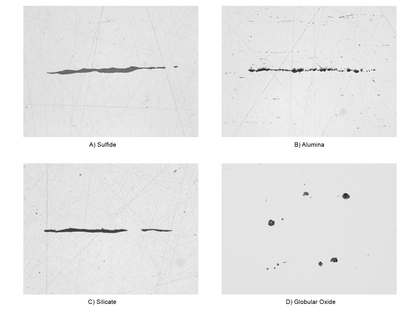
After proper sample preparation, nonmetallic inclusions can be observed directly on the surface of a given steel sample using a compound microscope (either an upright or inverted model) that can produce reflected light, brightfield conditions. Inclusions are easy to observe and analyze due to their high contrast ratio; inclusions appear dark on the bright, highly reflective background of steel. Morphological parameters differ between inclusion types (i.e., globular oxide and silicate) as do their grayscale values (i.e., alumina and sulfide).
Thanks to the continuous development of modern image analysis software, any user can start working immediately with a fully integrated digital solution for rating nonmetallic inclusions in steel that specifically caters to the requirements of a laboratory environment. Designed with ASTM E45 in mind (as well as other international standards), materials science software for metallurgical microscopes enable users of all skill levels to rate inclusions in steel accurately and repeatedly, with minimal training.
Recommended Equipment for Analyzing Nonmetallic Inclusions in Steel
A typical equipment configuration for analyzing nonmetallic inclusions in steel through digital image analysis consists of the following components:
1. Inverted Metallurgical Microscope
An inverted microscope is typically preferred over an upright model because the flat, polished sample lays flat on the mechanical stage. This helps ensure consistent focus as the user maneuvers the scanning stage.
2. Metallurgical-Specific Image Analysis Software
Because of their inherent high contrast level as well as their unique morphological parameters, nonmetallic inclusions in steel can be accurately, repeatedly, and easily detected using image analysis software. Image analysis software for materials science applications often offer optional add-on modules that enable users to obtain results in compliance with ASTM E45, as well as various international standards.
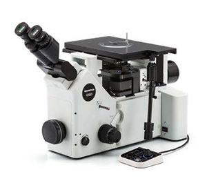 | 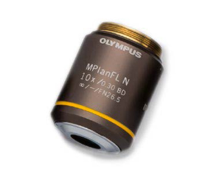 | 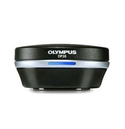 |
Typical equipment configuration: inverted metallurgical microscope, 10X metallurgical objective lens, and a high-resolution microscope camera
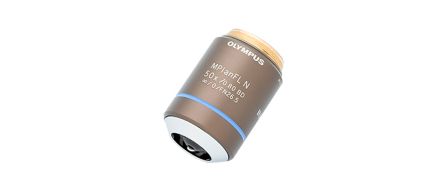
3. 10X Metallurgical Objective Lens
This is the required objective magnification for rating nonmetallic inclusions.
4. CCD or CMOS Digital Microscope Camera
The most important specification to consider when choosing a camera for rating inclusions is the pixel size. According to the ASTM E45 standard, a calibrated digital pixel size of
1.0 μm/pixel or better is required. For example, a digital camera with an uncalibrated, actual pixel size of 6.3 μm or finer is required when using a 10X objective lens and 0.63X camera adapter.
Calibrated digital resolution = (Actual pixel size) ÷ (Objective lens magnification) ÷ (Camera adapter magnification)
Calibrated digital resolution = (6.3 μm) ÷ (10) ÷ (0.63)
Calibrated digital resolution = 1 μm per pixel
A coded manual or motorized revolving-objective nosepiece is recommended. The chosen image analysis software should be capable of automatically reading the objective lens magnification at all times. This helps ensure the highest level of measurement accuracy, as automatic recognition helps eliminate the risk of manually entering the incorrect lens magnification in the software.
A manual or motorized XY scanning stage is required to manipulate the sample and position the area of interest for observation and analysis. However, since ASTM E45 states that an area of at least 160 mm2 must be scanned for analysis, it is recommended to use a motorized stage so that you can program it to scan an area that conforms with the standard.
The PC that you choose should meet the minimum system requirements of the camera and image analysis software. A high-resolution monitor is also required.
Procedure to Analyze Nonmetallic Inclusions in Steel
1. Select the 10X objective lens. Under reflected light and brightfield conditions, maneuver the sample on the XY stage to view the area of interest, which contains the inclusions to be analyzed. Alternatively, if you are using a motorized stage, program the software so that the stage will scan the required area of interest (at least 160 mm2 in the case of ASTM E45).
2. Capture the digital image via the image analysis software.
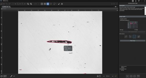
3. Within the inclusion rating software, set the grayscale threshold values to define all inclusions and to differentiate between oxides and sulfides, respectively. This will enable the image analysis software to differentiate between the two types.
4. The software analyzes the image and rates the inclusions’ compliance with the chosen standard.
 | 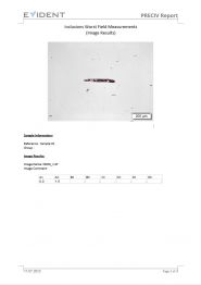 |
5. Based on a user’s predefined template, the software automatically generates a report that incorporates the analysis results, supporting inclusion images, and relevant data.
Other Ways to Streamline Nonmetallic Inclusion Analysis
Due to the inherent high contrast ratio between nonmetallic inclusions in steel and their metallic background, nonmetallic inclusions can be rated accurately and repeatedly using modern image analysis software for materials science applications. Many software packages are designed to comply with ASTM E45 and a wide range of international standards, and they can be implemented with minimal effort. Going beyond the scope of the nonmetallic inclusion analysis, many software programs offer convenient connectivity, reporting, and data management capabilities to save time. Software with automatic report generation, data archiving and sharing, and quick searches of images and related data can make your team more efficient. When considering a solution for rating nonmetallic inclusions, working directly with an experienced microscope manufacturer is highly important, as they can assist you in every step of this process, from equipment selection to deployment.
References
Carmo Pelliciari, Dr. Eng., Metallurgical Consultant
American Society for Testing and Materials (ASTM) E45-11 Standard
ASTM International, 100 Barr Harbor Drive, PO Box C700, West Conshohocken, PA, 19428-2959 USA


