A Review of Conventional Beam Characteristics
Conventional single element longitudinal wave ultrasonic transducers work as a piston source of high frequency mechanical vibrations, or sound waves. As voltage is applied, the piezoelectric transducer element (often called a crystal) deforms by compressing in the direction perpendicular to its face. When the voltage is removed, typically less than a microsecond later, the element springs back, generating the pulse of mechanical energy that comprises an ultrasonic wave. The graphic below shows a conceptualized example of how a piezoelectric element responds to a brief electrical pulse .
Transducers of the kind most commonly used for ultrasonic NDT will have these fundamental functional properties:
Type -- The transducer will be identified according to function as a contact, delay line, angle beam, or immersion type. Inspected material characteristics such as surface roughness, temperature, and accessibility as well as the position of a defect within the material and the inspection speed will all influence the selection of transducer type.
Diameter -- The diameter of the active transducer element, which is normally housed in a somewhat larger case.
Frequency -- The number of wave cycles completed in one second, normally expressed in Kilohertz (KHz) or Megahertz (MHz). Most industrial ultrasonic testing is done in the frequency range from 500 KHz to 20 MHz, so most transducers fall within that range, although commercial transducers are available from below 50 KHz to greater than 200 MHz. Penetration increases with lower frequency, while resolution and focal sharpness increase with higher frequency.
Bandwidth -- The portion of the frequency response that falls within specified amplitude limits. In this context, it should be noted that typical NDT transducers do not generate sound waves at a single pure frequency, but rather over a range of frequencies centered at the nominal frequency designation. The industry standard is to specify this bandwidth at the -6dB (or half amplitude) point.
Waveform duration -- The number of wave cycles generated by the transducer each time it is pulsed. A narrow bandwidth transducer has more cycles than a broader bandwidth transducer. Element diameter, backing material, electrical tuning and transducer excitation method all impact waveform duration
Sensitivity -- The relationship between the amplitude of the excitation pulse and that of the echo received from a designated target.
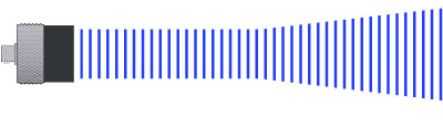
As a working approximation, the beam from a typical unfocused disk transducer is often thought of as a column of energy originating from the active element area that expands in diameter and eventually dissipates.
In fact, the actual beam profile is complex, with pressure gradients in both the transverse and axial directions. In the beam profile illustration below, red represents areas of highest energy, while green and blue represent lower energy.
The sound field of a transducer is divided into two zones, the near field and the far field. The near field is the region close to the transducer where the sound pressure goes through a series of maximums and minimums, and it ends at the last on-axis maximum at distance N from the face. Near field distance N represents the natural focus of the transducer.
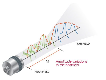
The far field is the region beyond N where the sound pressure gradually drops to zero as the beam diameter expands and its energy dissipates. The near field distance is a function of the transducer's frequency and diameter, and the sound velocity in the test medium, and it may be calculated as follows for the square or rectangular elements commonly found in phased array testing:
Because of the sound pressure variations within the near field, it can be difficult to accurately evaluate flaws using amplitude based techniques (although thickness gaging within the near field is not a problem). Additionally, N represents the greatest distance at which a transducer's beam can be focused by means of either an acoustic lens or phasing techniques. Focusing is discussed further in section 2.14, Focusing with Phased Array Probes.
The aspect radio constant is as follows, based on the ratio between the short and long dimensions of the element or aperture:
| Ratio short/long | k |
| 1.0 | 1.37 (square element) |
| 0.9 | 1.25 |
| 0.8 | 1.15 |
| 0.7 | 1.09 |
| 0.6 | 1.04 |
| 0.5 | 1.01 |
| 0.4 | 1.00 |
| 0.3 and below | 0.99 |
In the case of circular elements, k is not used and the diameter of the element (D) is used instead of the length term:
![]()