Ultrasonic Beam Characteristics
Transducers of the kind most commonly used for ultrasonic gauging will have these fundamental functional properties, which, in turn, affect the properties of the sound beam that they will generate in a given material:
Type - The transducer will be identified according to its design and function as a contact, delay line, or immersion type. Physical characteristics of the test material such as surface roughness, temperature, and accessibility, as well as its sound transmission properties and the range of thickness to be measured, will all influence the selection of transducer type.
Diameter - The diameter of the active transducer element, which is normally housed in a somewhat larger case. Smaller diameter transducers are often most easily coupled to the test material, while larger diameters may couple more efficiently into rough surfaces due to an averaging effect. Larger diameters are also required for design reasons as transducer frequency decreases.
Frequency - The number of wave cycles completed in one second, normally expressed in kilohertz (KHz) or megahertz (MHz). Most ultrasonic gauging is done in the frequency range from 500 KHz to 20 MHz, so most transducers fall within that range, although commercial transducers are available from below 50 KHz to greater than 200 MHz. Penetration increases with lower frequency, while resolution and focal sharpness increase with higher frequency.
Bandwidth - Typical transducers for thickness gauging do not generate sound waves at a single pure frequency, but rather over a range of frequencies centered at the nominal frequency designation. Bandwidth is the portion of the frequency response that falls within specified amplitude limits. Broad bandwidth is usually desirable in thickness gauging applications involving contact, delay line, and immersion transducers.
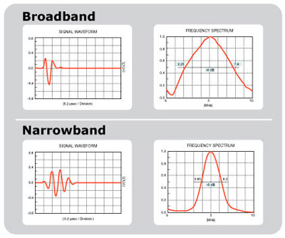
Waveform duration - The number of wave cycles generated by the transducer each time it is pulsed. A narrow bandwidth transducer has more cycles than a broader bandwidth transducer. Element diameter, backing material, electrical tuning, and transducer excitation method all impact waveform duration. A short wave duration (broadband response) is desirable in most thickness gauging applications.
Sensitivity - The relationship between the amplitude of the excitation pulse and that of the echo received from a designated target. This is a function of the energy output of the transducer.
Beam profile - As a working approximation, the beam from a typical unfocused disk transducer is often thought of as a column of energy originating from the active element area that travels as a straight column for a while and then expands in diameter and eventually dissipates, like the beam from a spotlight.
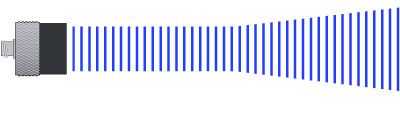
In fact, the actual beam profile is complex, with pressure gradients in both the transverse and axial directions. In the beam profile illustration below, red represents areas of highest energy, while green and blue represent lower energy.
![]()
The exact shape of the beam in a given case is determined by transducer frequency, transducer diameter, and material sound velocity. The area of maximum energy a short distance beyond the face of the transducer marks the transition between beam components known as the near field and the far field, each of which is characterized by specific types of pressure gradients. Near field length is an important factor in ultrasonic flaw detection, since it affects the amplitude of echoes from small flaws like cracks, but it is usually not a significant factor in thickness gauging applications.
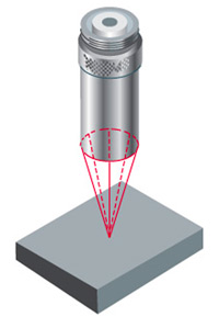
Focusing - Immersion transducers can be focused with acoustic lenses to create an hourglass-shaped beam that narrows to a small focal zone and then expands. Certain types of delay line transducers can be focused as well. Beam focusing is very useful when measuring small diameter tubing or other test pieces with sharp radiuses, since it concentrates sound energy in a small area and improves echo response.
Attenuation - As it travels through a medium, the organized wave front generated by an ultrasonic transducer will begin to break down due to imperfect transmission of energy through the microstructure of any material. Organized mechanical vibrations (sound waves) turn into random mechanical vibrations (heat) until the wave front is no longer detectable. This process is known as sound attenuation. Attenuation varies with material and increases proportionally to frequency. As a general rule, hard materials like metals are less attenuating than softer materials like plastics. Attenuation ultimately limits the maximum material thickness that can be measured with a given gauge setup and transducer, since it determines the point at which an echo will be too small to detect.