Theory of Operation
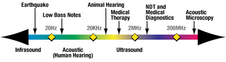
Sound waves are all around us, as mechanical vibrations carried by a medium such as air or water. Ultrasonic testing involves frequencies beyond the upper limit of human hearing, higher than 20 KHz and most commonly in the range from 500 KHz to 20 MHz, although higher and lower frequencies are sometimes used as well. The exact test frequency will be selected with respect to the specific application at hand. All ultrasonic thickness gauges work by very precisely measuring how long it takes for a sound pulse that has been generated by a probe called an ultrasonic transducer to travel through a test piece. Sound waves will reflect from boundaries between dissimilar materials, such as the air or liquid on the inside of a steel pipe wall, so this measurement can normally be made from one side in a "pulse/echo" mode.
The transducer contains a piezoelectric element which is excited by a short electrical impulse to generate a burst of ultrasonic waves. The sound waves are coupled into the test material and travels through it until they encounter a back wall or other boundary. The reflections then travel back to the transducer, which converts the sound energy back into electrical energy. In essence, the gauge listens for the echo from the opposite side. Typically this time interval is only a few millionths of a second. The gauge is programmed with the speed of sound in the test material, from which it can then calculate thickness using the simple mathematical relationship
T = (V) x (t/2)
where
T = the thickness of the part
V = the velocity of sound in the test material
t = the measured round-trip transit time
In some cases a zero offset is also subtracted to account for fixed delays in the instrument and soundpath.
It is important to note that the velocity of sound in the test material is an essential part of this calculation. Different materials transmit sound waves at different velocities, generally faster in hard materials and slower in soft materials, and sound velocity can change significantly with temperature. Thus, it is always necessary to calibrate an ultrasonic thickness gauge to the speed of sound in the material being measured, and accuracy can be only as good as this calibration. This is normally done with a reference standard whose thickness is precisely known. In the case of high-temperature measurements, it is also necessary to remember that sound velocity changes with temperature, so for optimum accuracy, the reference standard should be at the same temperature as the test piece.
Higher frequencies have a shorter associated wavelength, permitting measurement of thinner materials. Lower frequencies with a longer wavelength will penetrate farther and are used to test very thick samples, or for materials like fiberglass and coarse-grained cast metals that transmit sound waves less efficiently. Selection of an optimum test frequency often involves balancing these requirements for resolution and penetration. In the ultrasonic frequency range, sound waves are highly directional, and while they will travel freely through typical metals, plastics, and ceramics, they will reflect from an air boundary such as an inner wall or a crack.
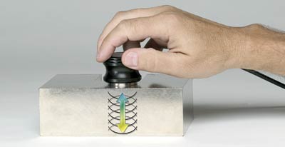
Sound waves in the megahertz range do not travel efficiently through air, so a drop of coupling liquid is used between the transducer and the test piece to achieve good sound transmission. Common couplants are glycerin, propylene glycol, water, oil, and gel. Only a small amount is needed, just enough to fill the extremely thin air gap that would otherwise exist between the transducer and the target.
A block diagram of a typical ultrasonic thickness gauge is seen below. The pulser, under the control of the microprocessor, provides a voltage impulse to the transducer, generating the outgoing ultrasonic wave. Echoes returned from the test piece are received by the transducer and converted back into electrical signals, which, in turn, are fed into the receiver amplifier and then digitized. The microprocessor-based control and timing logic both synchronizes the pulser and selects the appropriate echoes that will be used for the time interval measurement.
If echoes are detected, the timing circuit will precisely measure a time interval in one of the modes discussed in Section 3, and then typically repeat this process several times to obtain an averaged reading. The microprocessor then uses this time interval measurement along with programmed sound velocity and zero offset values to calculate thickness. Finally, the thickness is displayed and updated at a selected rate.