Velocity and Zero Calibration
In velocity calibration, the gauge measures the speed of sound in a reference sample of the test material and then stores that value for use in calculating thickness from measured time intervals. Major factors that effect sound velocity are material density and elasticity, material composition, grain structure, and temperature.
In zero calibration, the gauge uses a measurement of a material sample of known thickness to calculate a zero offset value that compensates for the portion of the total pulse transit time that represents factors other than the actual sound path in the test piece. Major factors that are included together in the zero value are electronic switching delays in the gauge, cable delays, transducer delays, and the couplant delays. In the case of contact transducers, the transducer delay comprises the amount of time it takes for sound energy to exit the transducer through its protective wearplate. In the case of dual element transducers, the transducer delay is the amount of time it takes for sound energy to pass through the transducer's delay lines or standoff. (In Mode 2 and Mode 3 measurements, where timing is performed from an interface echo representing the point at which sound energy enters the test piece, the transducer component of the zero offset value is generally zero.)
The recommended procedure for velocity and zero calibration is a "two-point calibration", which requires two samples of the test material of different thicknesses, within the thickness range to be measured, and whose thicknesses are precisely known. These do not have to be commercial test blocks, as long as their thickness is known. It is much more important that the material used for calibration be exactly the same as the material being measured and ideally have the same surface finish as well. The two blocks should have a 2:1 or greater thickness ratio, with a 5:1 or greater ratio being optimum.
A common calibration sequence is as follows:
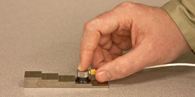
(1) Couple the transducer to the thick reference sample.
(2) Using the keypad, enter the "calibrate velocity" command.
(3) When the thickness reading is stable, press ENTER.
(4) Using the keypad, adjust the displayed value to correspond to the actual thickness of the thick reference sample.
(5) Couple the transducer to the thin reference sample.
(6) Using the keypad, enter the "calibrate zero" command.
(7) When the thickness reading is stable, press ENTER.
(8) Using the keypad, adjust the displayed value to correspond to the actual thickness of the thin reference sample.
(9) Press the MEASURE key to complete the process.
Using the four available data points, the two entered thickness values plus the measured transit time associated with each, the gauge calculates the unique velocity and zero values that solve that equation. Those values will then be used for measurements and can be stored as part of a setup.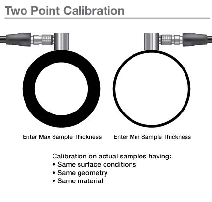
Following two-point calibration, a good practice is to check readings on one or more additional reference standards whose thickness lies between the values used for the calibration. Incorrect coupling or numerical entry will result in errors, as will use of calibration standards whose thickness is outside the valid measurement range for a given gauge, transducer, and setup. If the thickness reading is incorrect and error increases as thickness increases, then the error is most likely in the velocity value. If the thickness is incorrect by a fixed amount on multiple steps, then the error is most likely error in the zero calibration. In either case the two-point calibration process should be repeated.