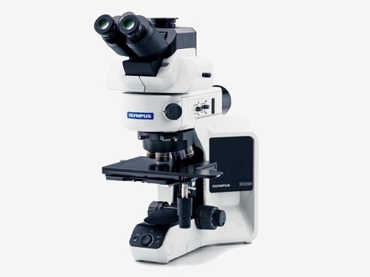
Highly Reliable Modular SystemSix BX53M suggested configurations provide you with flexibility to choose the features that you need. |
| General Use | Dedicated Use | |||||||||
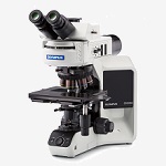
EntryEasy setup with basic features | Standard
Simple to use with
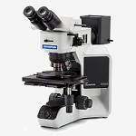
| AdvancedSupports numerous advanced features | Fluorescence
Ideally suited for
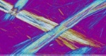
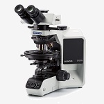
| InfraredDesigned to use infrared observation to inspect integrated circuits | PolarizationDesigned for observing birefringence characteristics | |||||
LCD color filter |
Microstructure with ferritic |
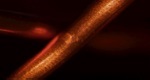
Copper wire of coil |
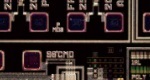
Resist on IC pattern |
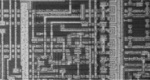
Silicon layering IC pattern |
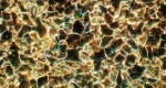
Asbestos | |||||
|
|
|
|
|
| |||||

See Specification Chart
| Entry | Standard | Advanced | Fluorescence | Infrared | Polarization | |
| Microscope frame | Reflected or Reflected/Transmitted | Reflected or Reflected/Transmitted | Reflected | Transmitted | ||
| Standard | R-BF or T-BF | R-BF or T-BF or DF | R-BF or T-BF or DF or MIX | R-BF or T-BF or DF or FL | R-BF or IR | T-BF or POL |
| Option | DIC | DIC/MIX | DIC | DIC/MIX | - | - |
| Simple illuminator | - |  | | - | - | - |
| Aperture legend | - | | | | - | |
| Coded hardware | - | | | | - | |
| Focus scale index | | | | | | |
| Light intensity manager | | | | - | - | |
| Hand switch operation |  | | | | - | - |
| MIX observation | | | | | - | - |
| Objectives | Select from 3 objectives based on your applications | Select from 3 objectives based on your applications | Objectives for IR | Objectives for POL | ||
| Stage | Select from 5 stages based on the size of your samples | Select from 5 stages based on the size of your samples | Stage for POL | |||
OBSERVATION METHOD
R-BF: Brightfield (Reflected)
*T-BF can be used when selecting Reflected/Transmitted microscope frame.
|
Example Configurations for Materials Science
Modular design enables various configurations to meet users’ requirements.
|
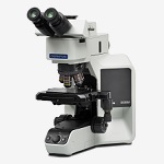
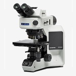
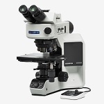
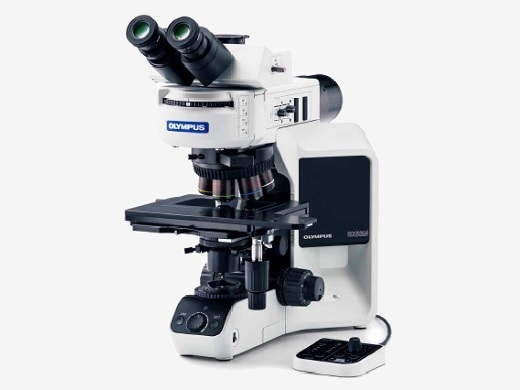
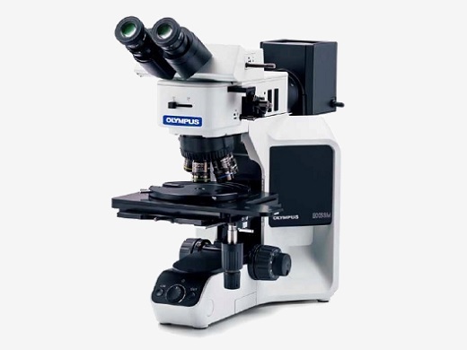
BX53M Reflected and Reflected/Transmitted Light CombinationThere are two types of microscope frames in the BX3M series, one for reflected light only and one for both reflected and transmitted light. Both frames can be configured with manual, coded, or motorized components. The frames are outfitted with ESD capability to protect electronic samples. |
BX53MRF-S example configuration |
BX53MTRF-S example configuration |
|---|
 | BX53M IR CombinationIR objectives can be used for semiconductor inspection, measurement, and processing applications where imaging through silicon is required to see the pattern. 5X to 100X infrared (IR) objectives are available with chromatic aberration correction from visible light wavelengths through the near infrared. For high magnification work, rotating the correction collar of the LCPLNIR series of lenses corrects for aberrations caused by sample thickness. A clear image is obtained with a single objective. Click here for details about IR objective lenses |
|---|
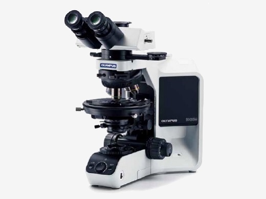
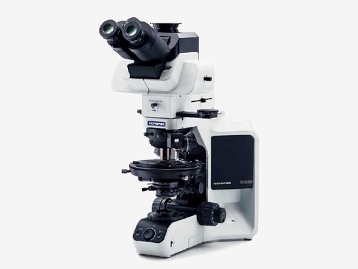
BX53M Polarized Light CombinationThe optics of the BX53M polarized light provide geologists with the right tools for high-contrast polarized light imaging. Applications such as mineral identification, investigating the optical characteristics of crystals, and observing solid rock sections benefit from system stability and precise optical alignment. |
BX53-P orthoscopic configuration |
BX53-P conoscopic/orthoscopic configuration |
|---|
Bertrand Lens for Conoscopic and Orthoscopic ObservationsWith a U-CPA conoscopic observation attachment, switching between orthoscopic and conoscopic observation is simple and fast. It is focusable for clear back focal plane interference patterns. The Bertrand field stop makes it possible to obtain consistently sharp and clear conoscopic images. | 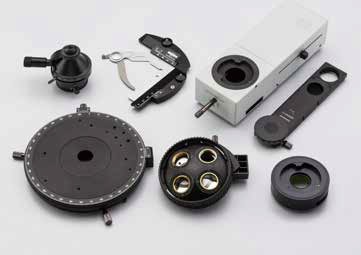 |
|---|
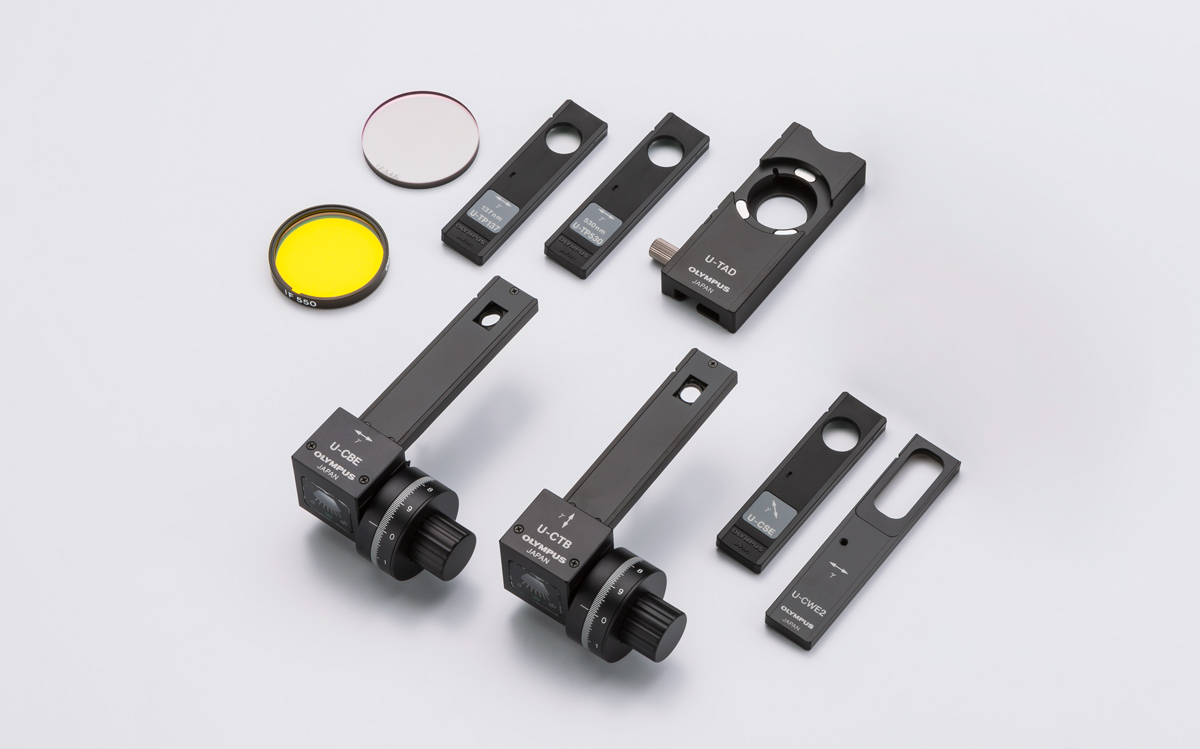 | An Extensive Range of Compensator and Wave PlatesFive different compensators are available for measurements of birefringence in rock and mineral thin sections. Measurement retardation level ranges from 0 to 20λ. For easier measurement and high image contrast, the Berek and Senarmont compensators can be used, which change the retardation level in the entire field of view. |
|---|
Measuring Range of Compensators
|
*R = retardation level |
Strain Free OpticsThanks to our sophisticated design and manufacturing technology, the UPLFLN-P strainfree objectives reduce internal strain to the minimum. This means a higher EF value, resulting in excellent image contrast. | Click here for details about UPLFLN-P objective lensesClick here for details about PLN-P / ACHN-P objective lenses |
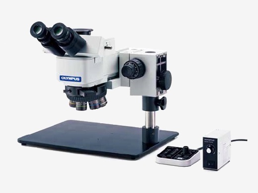 | BXFM SystemThe BXFM can be adapted to special applications or integrated into other instruments. The modular construction provides for straightforward adaptation to unique environments and configurations with a variety of special small illuminators and fixturing mounts. |
|---|
Modular Design, Build Your System Your Way |
Microscope FramesThere are two microscope frames for reflected light, one also has transmitted Light; capability. An adapter is available to raise the illuminator to accommodate taller samples.
Convenient Accessories for Microscopy use
|
|
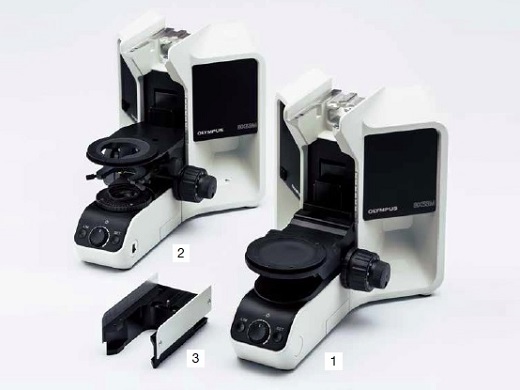
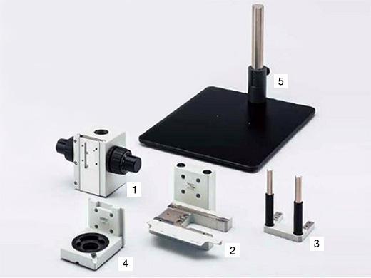
StandsFor microscopy applications where the sample will not fit on a stage, the illuminator and optics can be mounted to a larger stand or to another piece of equipment. BXFM + BX53M Illuminator Configuration
BXFM + U-KMAS Illuminator Configuration
|
|
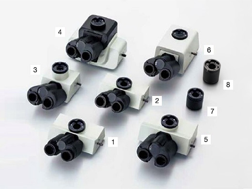
TubesFor microscope imaging with eyepieces or for camera observation, select tubes by imaging type and operator’s posture during observation.
|  |
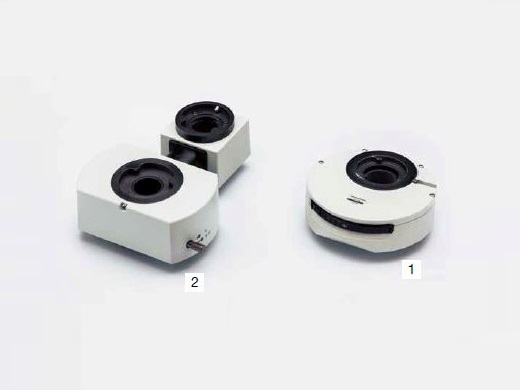
IlluminatorsThe illuminator projects light onto the sample based on the observation method selected. Software interfaces with coded illuminators to read the cube position and automatically recognize the observation method. | 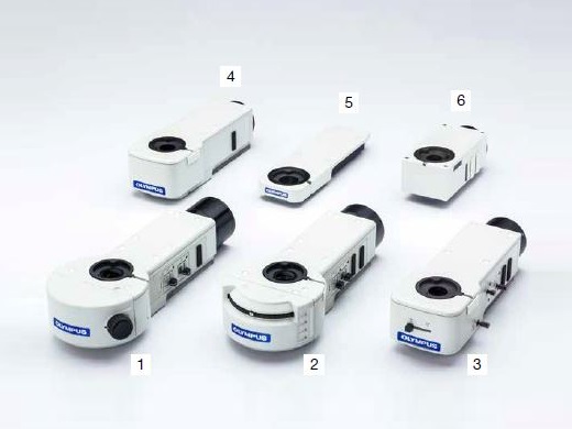 |
| Coded function | Light source | BF | DF | DIC | POL | IR | FL | MIX | AS/FS | ||
| 1 | BX3M-RLAS-S | Fixed 3 cube position | LED - Built in | ■ | ■ | ■ | ■ | - | - | ■ | ■ |
| 2 | BX3M-URAS-S | Attachable 4 cube position | LED | ■ | ■ | ■ | ■ | - | - | ■ | ■ |
| Halogen | ■ | ■ | ■ | ■ | ■ | - | ■ | ■ | |||
| Mercury/Light guide | ■ | ■ | ■ | ■ | - | ■ | ■ | ■ | |||
| 3 | BX3M-RLA-S | LED | ■ | ■ | ■ | ■ | - | - | ■ | ■ | |
| Halogen | ■ | ■ | ■ | ■ | ■ | - | ■ | ■ | |||
| 4 | BX3M-KMA-S | LED - Built in | ■ | - | ■ | ■ | - | - | ■ | - | |
| 5 | BX3-ARM | Mechanical arm for transmitted light | |||||||||
| 6 | U-KMAS | LED | ■ | - | ■ | ■ | - | - | ■ | - | |
| Halogen | ■ | - | ■ | ■ | ■ | - | ■ | - | |||
Light SourcesLight sources and power supplies for sample illumination, choose the appropriate light source for the observation method. | 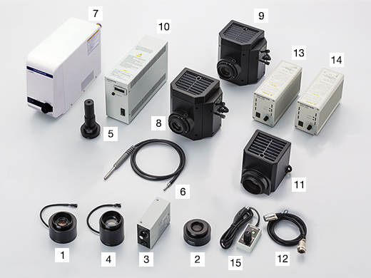 |
Standard LED Light Resource Configuration
Fluorescence Light Resource Configuration
| Halogen and Halogen IR Light Resource Configuration
|
NosepiecesAttachment for objectives and sliders. Select by the number of objectives needed and types; also with/without slider attachment. | 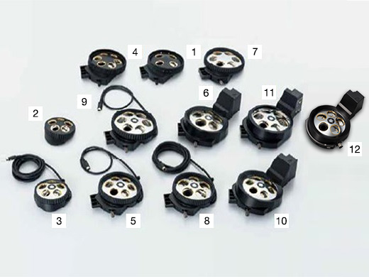 |
| Type | Holes | BF | DF | DIC | MIX | ESD |
Number of
centering holes | ||
| 1 | U-P4RE | Manual | 4 | ■ | ■ | 4 | |||
| 2 | U-5RE-2 | Manual | 5 | ■ | |||||
| 3 | U-5RES-ESD | Coded | 5 | ■ | ■ | ||||
| 4 | U-D6RE | Manual | 6 | ■ | ■ | ||||
| 5 | U-D6RES | Coded | 6 | ■ | ■ | ||||
| 6 | U-D5BDREMC | Motorized | 5 | ■ | ■ | ■ | ■ | ||
| 7 | U-D6BDRE | Manual | 6 | ■ | ■ | ■ | ■ | ||
| 8 | U-D5BDRES-ESD | Coded | 5 | ■ | ■ | ■ | ■ | ■ | |
| 9 | U-D6BDRES-S | Coded | 6 | ■ | ■ | ■ | ■ | ■ | |
| 10 | U-D6REMC | Motorized | 6 | ■ | ■ | ||||
| 11 | U-D6BDREMC | Motorized | 6 | ■ | ■ | ■ | ■ | ■ | |
| 12 | U-D5BDREMC-VA | Motorized | 5 | ■ | ■ |
SlidersSelect the slider to compliment traditional brighfield observation. The DIC slider provides topographic information about the sample with options to maximize contrast or resolution. The MIX slider provides illumination flexibility with a segmented LED source in the darkfield path. | 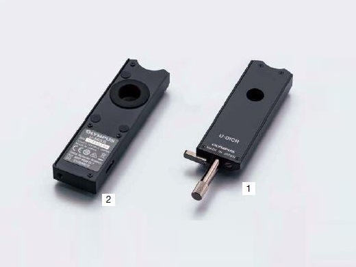 |
DIC Slider
*1 1.25X and 2.5X do not support DIC observation.
MIX Slider
| Cable
*MIXR only |
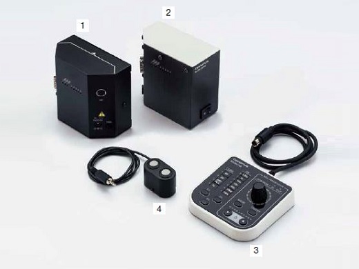
Controls Box and Hand SwitchesControl boxes for interfacing microscope hardware with a PC and hand switches for hardware display and control. BX3M-CB (CBFM) Configuration
Cable
|
|
StagesStages and stage plates for sample placement. Select based on sample shape and size. | 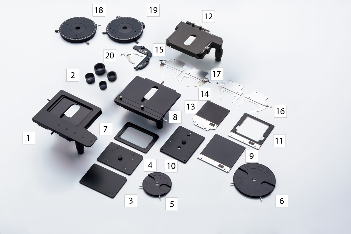 |
150 mm × 100 mm Stage Configuration
76 mm × 52 mm Stage Configuration
| 100 mm × 100 mm Stage Configuration
Others
|
Camera AdaptersAdapter for camera observation. Selectable from required field of view and magnification. Actual observation range can be calculated using this formula: actual field of view (diagonal mm) = viewing field (viewing number) ÷ objective magnification. | 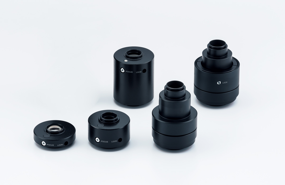 |
| Magnification | Centering adjustment | CCD image area (field number) mm | ||||
| 2/3 inch | 1/1.8 inch | 1/2 inch | ||||
| 1 | U-TV1x-2 with U-CMAD3 | 1 | - | 10.7 | 8.8 | 8 |
| 2 | U-TV1xC | 1 | ø2 mm | 10.7 | 8.8 | 8 |
| 3 | U-TV0.63xC | 0.63 | - | 17 | 14 | 12.7 |
| 4 | U-TV0.5xC-3 | 0.5 | - | 21.4 | 17.6 | 16 |
| 5 | U-TV0.35xC-2 | 0.35 | - | - | - | 22 |
EyepiecesEyepiece for viewing directly into the microscope. Select based on desired field of view.
| 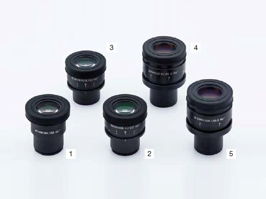 |
Optical FiltersOptics filters convert sample exposure light to various types of illumination. Select the appropriate filter for observation requirements. | |
BF, DF, FL
POL, DIC
| IR
Transmitted Light
Others
*AN and PO are not necessary when using BX3M-RLAS-S and U-FDICR |
CondensersCondensers collect and focus transmitted light. Use for transmitted light observation.
| 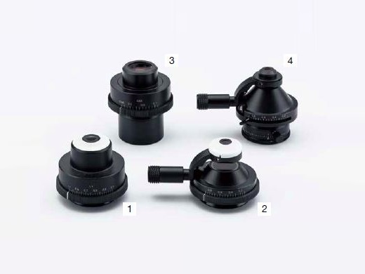 |
Mirror UnitsMirror unit for BX3M-URAS-S. Select the unit for required observation.
*For coaxial episcopic illumination only | 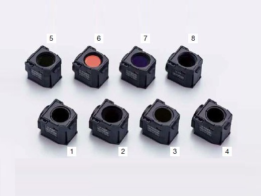 |
Intermediate TubesVarious types of accessories for multiple purposes. For use between tube and illuminator.
|  |
UIS2 ObjectivesObjectives magnify the sample. Select the objective that matches the working distance, resolving power and observation method for the application. |