Technique facilitates even illumination and excellent specimen contrast
Critical illumination was the predominant technique in microscopy until August Köhler (1866–1948) developed a new method of illumination, now known as Köhler illumination. The problem with critical illumination was that the bright light lamp source created a filament image in the same plane as the specimen image. Visibility of the bulb filament in the final image caused uneven specimen illumination and introduced glare and shadowing artifacts. Köhler illumination resolved these artifacts by using a defocused light source image to evenly illuminate the specimen.
Still relevant today, Köhler illumination should be applied whenever suboptimal specimen illumination is preventing proper observation. Köhler illumination can provide even illumination of specimens in brightfield, darkfield, and all variations of phase contrast microscopy using either transmitted or reflected light pathways. Köhler illumination facilitates even illumination, high resolution, and good specimen contrast.
 |
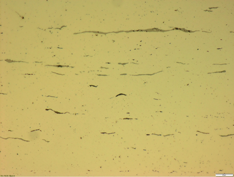 |
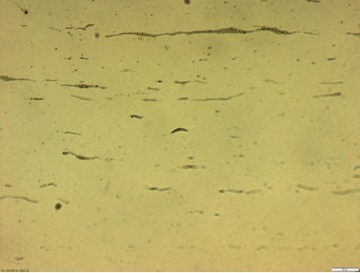
| An image captured with reflected light microscopy. The above image was captured without Köhler illumination and the bottom with Köhler illumination. |
How do you set up and use Köhler illumination?
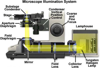
Transmitted light microscopy: Köhler illumination requires several optical components of the microscope to function in between the light source and the specimen. These include the collector lens, field diaphragm, condenser diaphragm, and condenser lens. The collector lens acts to collect light from the light source and focus it on the plane of the condenser diaphragm. The condenser lens then projects this light through to the specimen.
By adjusting the field diaphragm, the image of the field diaphragm aperture in the specimen plane is set to a size slightly larger than the imaged region of the specimen, which corresponds to the portion of the specimen image seen at the eyepiece field stop. As the field diaphragm, specimen, and eyepiece field stop all lie on the same conjugate image plane, this adjustment allows the illuminating rays to completely fill the eyepiece field of view, while minimizing the amount of extraneous light blocked by the eyepiece field stop.
 |
Reflected light microscopy: Reflected light microscopy or epi-illumination is the choice for illumination of opaque specimens like metals, ores, ceramics, polymers, semiconductors (e.g., unprocessed silicon, wafers, integrated circuits), slag, coal, plastics, and paint.
The key optical components needed to set up Köhler illumination in reflected light microscopy are arranged in opposite orientation to those in transmitted light microscopy. The condenser aperture iris diaphragm is closer to the light source and the field iris diaphragm is closer to the specimen. In reflected light microscopy, the objective serves a dual function—on the way down, the objective serves as a properly aligned condenser, controlling the angle of the light striking the specimen. On the way up, the objective’s numerical aperture (NA) determines the angle of light which can be captured as it is reflected from the specimen. All things being equal, the higher the NA, the better the resolution of the objective, and the better the resolution of the specimen.
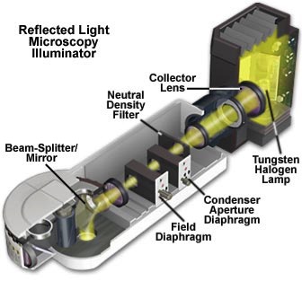 |
| Typical setup for a reflected light microscope. |
How are Köhler illumination techniques applied?
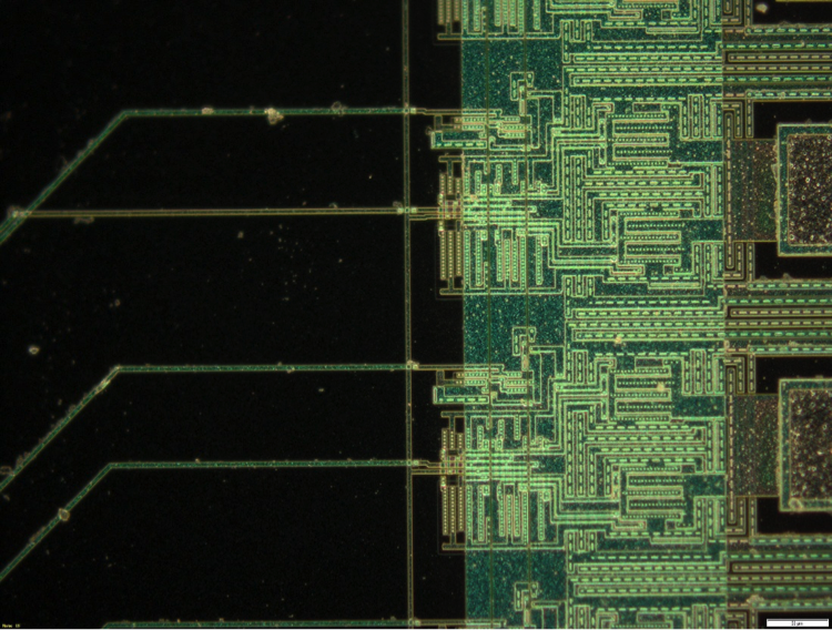
Brightfield microscopy: The most commonly used optical microscopy technique. Illumination of the sample is transmitted from above via a tungsten-halogen lamp focused through the vertical illuminator positioned above the stage. Light reflected by a beam splitter through the objective illuminates the specimen. Light reflected from the specimen surface re-enters the objective and passes into the eyepiece or to a camera port. Absorption and diffraction of the incident light by the specimen often lead to discernible variations in the image. Specimens that show little difference in intensity or color require dark field microscopy or reflected differential interference contrast (DIC) (see below).
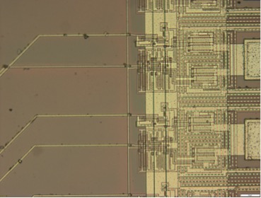 |
| An image of a microchip under brightfield observation. |
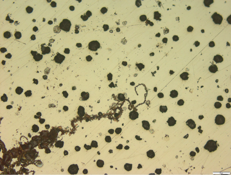
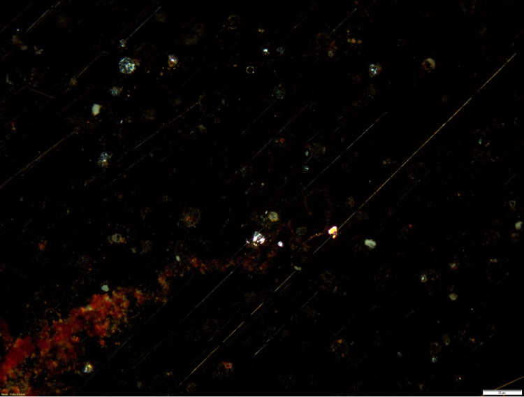
Darkfield microscopy: Well-suited for applications where contrast comes from light scattered by the specimen. Light not scattered by the specimen is not collected by the objective lens and not incorporated into the image. Consequently, the field around the specimen appears dark. The main limitation of darkfield microscopy is the low light levels seen in the final image. This is how Köhler illumination techniques contribute—the sample must be strongly illuminated. Raised features that are too smooth to cast shadows will not appear in brightfield images, but the light that reflects off the sides of the feature will be visible in the darkfield images.
 |
| An image of a microchip under darkfield observation. |
Phase contrast microscopy: An optical microscopy technique that generates sample contrast from interference of different path lengths of light reflected from the specimen. Amplitude and phase shifts occur based on properties of the specimen. These changes show as variations in brightness from the scattering and absorption of light. Phase contrast microscopy is particularly important in industrial microscopy as it reveals many features or structures of a specimen not visible in brightfield microscopy.
 |
 |
| An image of cross-sectioned polished metal under brightfield observation with no phase contrast (top) and with phase contrast (below). |
Differential interference contrast (DIC microscopy): A new phase contrast imaging method. DIC microscopy enhances contrast by creating artificial shadows, as if the object is illuminated from the side. To achieve DIC microscopy, polarized light is separated into two orthogonally polarized parts. The mutually coherent parts, which are spatially displaced (sheared) at the specimen plane, are then recombined before observation. The interference of the two parts at recombination is sensitive to their optical path differences, the product of their refractive index and geometric path length. The observed contrast is proportional to the path length gradient along the shear direction, giving the appearance of a three-dimensional physical relief.
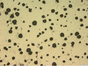 |
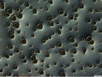 |
| An image of cross-sectioned polished metal under brightfield observation with no DIC (above) and with DIC (below). |