Carbon fiber reinforced polymer (CFRP) composites are lightweight yet strong plastic materials that contain carbon fibers. Due to their good mechanical properties, CFRP materials are used in a wide range of manufactured parts for automotive, aerospace, and other industries. As more CFRP parts are produced, it is important to find fast, effective inspection processes.
In a paper published in the program for the 19th World Conference on Nondestructive Testing (WCNDT), Jatzlau et al. found that the resonance mode of our BondMaster™ bond tester can easily, quickly, and cost-effectively detect qualitative differences in porosity of CFRP automotive manufactured parts.
The goal of their study was to examine nondestructive testing (NDT) methods of acoustic resonance analysis to identify the most effective quality assurance and inspection method of flaws in CFRP parts. The experiments conducted in the study used CFRP samples with flaws of impact damages, fiber waviness, and porosity. The authors selected the BondMaster bond tester to identify CFRP parts with manufacturing errors, as well as damage during operation.
The results of the paper conclude that, “Compared to other NDT methods such as ultrasound and thermography, acoustic resonance analysis allows a simple and quick identification of flawed parts including approximate flaw localization. Subsequently, the identified parts can be inspected more closely by means of more complex testing instruments to precisely examine location, type, and size of the flaw.”
To learn more about the experiment and results, read the full paper here.
The Role of Adhesive-Bonded Components and Structures in the Automotive Industry
Adhesive-bonded components and structures have become an important part of manufacturing in the automotive industry. The integrity and reliability of bonds are critical to producing high-quality end products.
Resonance testing can readily detect delaminations. This method also detects many types of disbonds (i.e., skin-to-core separation in honeycomb composite structures).
However, the setup and operation of resonance testing can be complicated. The testing requires a liquid couplant, which makes it harder to scan the joint. Liquid couplants are also not allowed for some composite materials and structures due to possible contamination.
The BondMaster 600 instrument offers bond testing methods that do not require couplant, such as pitch-catch and mechanical impedance analysis (MIA). The resonance inspection method, available on the BondMaster 600M model, is particularly good at detecting delaminations and disbonds in an array of composite structures. It works best on thin-skinned composites.
Resonance Mode Adhesive Bond Testing: How It Works
The resonance method uses special narrow-bandwidth ultrasonic contact probes. The method is based on the change in impedance of the sharply resonant high-Q ultrasonic transducer when acoustically coupled to a material. The measured electrical impedance of the transducer is affected by the acoustic impedance of the test sample. The acoustic impedance in a specific composite is altered by any lack of bonding.
A disbond acts as a thin plate that vibrates, generating a standing wave when the thickness is equal to odd number multiples (1, 3, 5, etc.) of the length of the acoustic wave in the plate.
For one wavelength: l = v/f, where v = sound velocity in the material and f is the resonance frequency. The thinner the layer, the higher the resonance frequency.
Figure 1 below shows a resonance transducer coupled to a test piece at a disbonded joint, and the resultant standing wave.
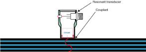
Figure 1. Resonant standing wave in a thin plate or disbonded joint.
For the acoustic impedance: Z = rVtanh[a +i(ß +kt)], where a is the reflectivity constant, ß is the phase change, t is the plate thickness, and k is the wave number.
In an adhesive-bonded joint, changes in the effective thickness caused by disbonding significantly affects the phase and amplitude of the signal at the resonance frequency of the transducer. In a multilayered joint, the phase is related to the depth of the disbonded layer, as shown in Figure 2.
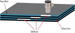
Figure 2. Multilayer disbond test.
The BondMaster 600M bond tester will automatically prompt the transducer’s resonance frequency in air by sweeping over a frequency range and locating the phase null.
The instrument then operates at that frequency. Figure 3 illustrates the correct operation of the probe.
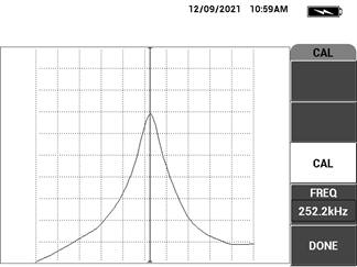
Figure 3. The BondMaster 600M instrument sweeps through the frequency range of a probe and displays the probe's resonance characteristics. Confirmation of the resonance frequency confirms the correct operation of the probe.
Coupling the probe to a composite part causes the part to act as a damping member, reducing the amplitude and increasing the bandwidth of the transducer, as well as changing the resonance frequency. The probe is nulled on the good bond/defect-free area, as seen in Figure 4 below.
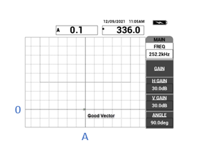
Figure 4. The probe is nulled on the good bond/defect-free area.
When there is a defect like a delamination, the defect will alter the probe’s resonance frequency, thereby altering the vector position displayed on the screen. The phase is indicated by the 0 of the vector and the amplitude, A by the distance from the center null point. The signals on the display will appear as shown in Figure 5 below.
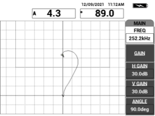
Figure 5. Example of a delamination detected on the BondMaster 600M instrument.
The frequency of the probe is chosen based on skin-layer thickness and material type. For optimal sensitivity to disbonds, the thinner the layer is, the higher the probe frequency should be.
The frequency of the probe should be proportional to the acoustic impedance of the layer. Materials such as graphite or fiberglass, with low impedance (Z = rV, where Z is the impedance, r is the density and V is the velocity of sound waves in the material), require lower-frequency probes than metal-skin layers.
Frequencies in the range of 35–350 kHz are useful for most bond testing, with the higher frequencies used for thinner or metallic layers.
Easy Inspection of Laminate Composites Using Bond Testing
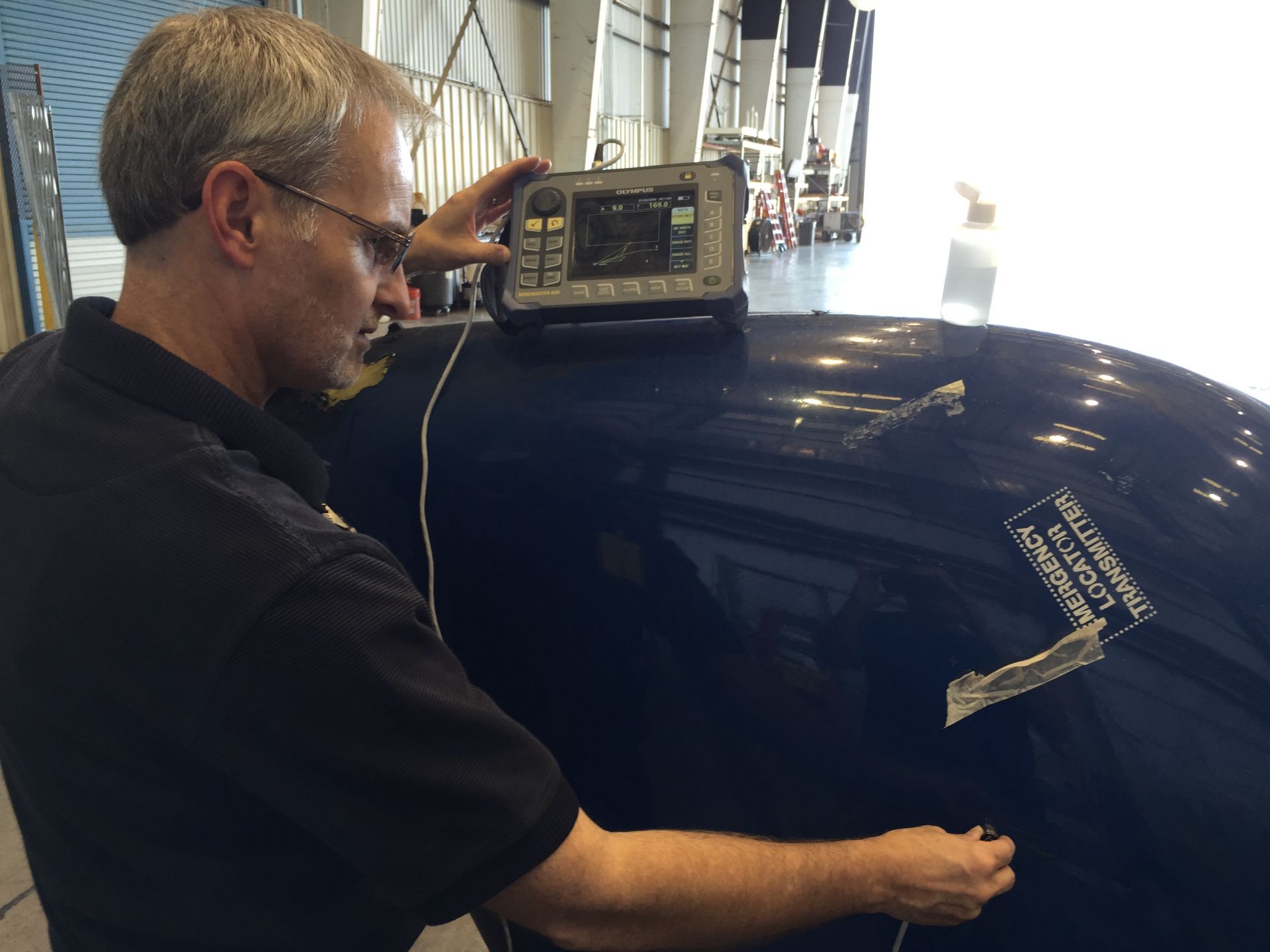
An operator uses the BondMaster 600 bond tester in resonance mode to inspect composite material.
The BondMaster 600M bond tester is programmed for a range of standard inspection methods, including pitch-catch RF, pitch-catch impulse, pitch-catch swept, resonance, as well as a notably improved mechanical impedance analysis (MIA) method. Resonance mode of the BondMaster 600M bond tester measures the changes in phase and amplitude of the propagating/standing wave within the probe. Resonance probes are narrow bandwidth contact transducers, and the changes in probe crystal impedance is represented in the X-Y display of the BondMaster 600M bond tester.
Resonance mode is a very simple and reliable way to detect delamination. Often, the depth of delamination can be estimated from signal phase rotation. Resonance mode on the BondMaster 600M bond tester is remarkably easy to operate, due in large part to its factory presets for laminate composite applications.
Easily Integrate Bond Testing into High-Speed Automated Systems

Similar to the NORTEC™ 600 eddy current flaw detector, the BondMaster 600 bond tester can be merged easily and seamlessly into integrated inspection systems and is built to perform consistently in industrial environments.
Learn more about bond testing in our white paper or contact us for an in-person or virtual demo.
Related Content
Multimode Adhesive Bond Testing
Composite Inspection Solutions
Video: An Advanced Guide to Finding the Correct Frequencies for Inspecting Honeycomb Composites
Get In Touch