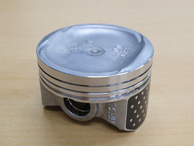
Piston
Burrs on Pistons in Car Engines
In a cylinder block’s combustion chamber, a piston often slides up and down several thousand times per minute at temperatures as high as several hundred degrees Celsius to generate enough power to drive the car. To operate correctly, the piston must have low thermal expansion, heat resistance, and abrasion resistance.
The piston must also be machined with no burrs so that it can slide smoothly and quickly. If there are burrs, particularly in the piston’s grooves, it can lead to engine issues. Since the grooves accommodate piston rings, which slide in direct contact with the cylinder liner, a burr can cause the piston ring to fit improperly and result in issues with combustion in the engine.
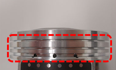
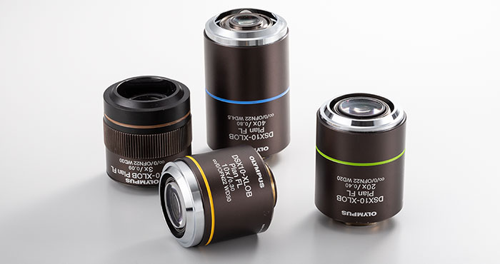
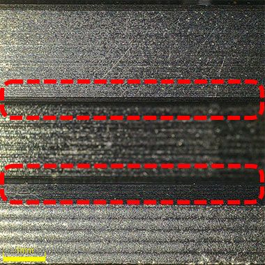
The red dotted rectangle shows piston ring grooves without any burrs.
|
|
Piston cross section | |
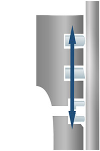
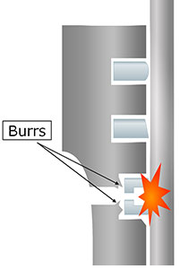
Piston ring grooves with no burrs A groove without burrs ensures the piston ring fits properly. The piston can slide smoothly along the cylinder liner. | Piston ring grooves with a burr If a groove has burrs, the piston ring protrudes from the groove and may cause several problems:
|
Inspecting pistons for burrs using a microscope can help prevent these issues. First, inspectors must conduct a low-magnification observation to check for burrs. Then high-magnification images are needed to analyze any identified burrs.
Digital microscopes are often used for these inspections because there is no need to cut or damage the pistons for the observations. However, pistons can be difficult to observe under a microscope due to their cylindrical shape and the several-millimeter depth of the piston ring grooves. As a result, these inspections require skilled technicians.
Benefits of Inspecting Burrs on Pistons Using the DSX1000 Digital Microscope
The DSX1000 digital microscope offers several benefits to overcome these challenges and create a more intuitive, efficient workflow that inspectors of any skill level can perform.
1. Observe small burrs with clear images at low magnification
The DSX1000 digital microscope is equipped with dedicated objective lenses that can provide clear images at low magnifications. With these lenses, you can observe very small burrs.
XLOB long working distance DSX objectives
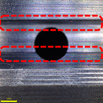 42x image focused on the top of a piston ring groove. You can clearly see the condition of the groove edges. | 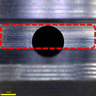 42x image focused on the bottom of a piston ring groove. You can clearly see that there are no burrs. |  42x image focused on both the top and bottom of a groove using the omnifocal function. You can clearly see the edge of the cooling channel hole. |
2. See the piston ring groove from different angles with a tilting frame
Thanks to the DSX1000 microscope’s optical design, the field of view remains in place even when the head is tilted. This flexible tilting frame enables you to easily observe a ring groove all around the piston’s outer circumference.
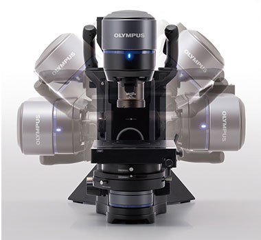
Tilting head of the DSX1000 microscope
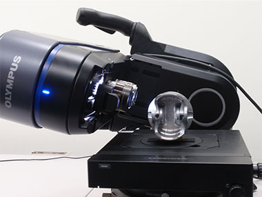
Easily observe cylindrical pistons by accurately aiming at the part of interest from an angle.
42x image acquired with the DSX1000 microscope head tilted at a 70º angle.
You can clearly see the edges of the piston ring groove.
3. Instantly switch to a higher magnification objective to analyze burrs
After a burr is detected, inspectors need to observe and analyze its condition in more detail. Most conventional digital microscopes only offer one lens, making this step difficult. While zooming in with the lens increases the magnification of an image, it cannot improve the image quality.
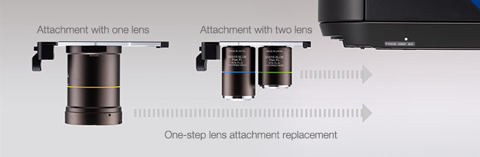
To acquire high-quality, high-magnification images, you must replace the mounted objective lens with a high-resolution, high-power objective lens. The DSX1000 digital microscope offers a head that can mount up to two objectives simultaneously, enabling you to change the magnification simply by sliding the objective lenses.

In addition, you can mount a new objective lens in one step by inserting an attachment with the lens into the head. The lens attachment features a built-in sensor, enabling the microscope to know which lens you’re using, including the field of view and magnification.
 High-magnification (500x) image of the edge of a piston ring groove. You can clearly see that the edge is straight. |  High-magnification (500x) image of the bottom of a piston ring groove. You can closely observe the machined state. |